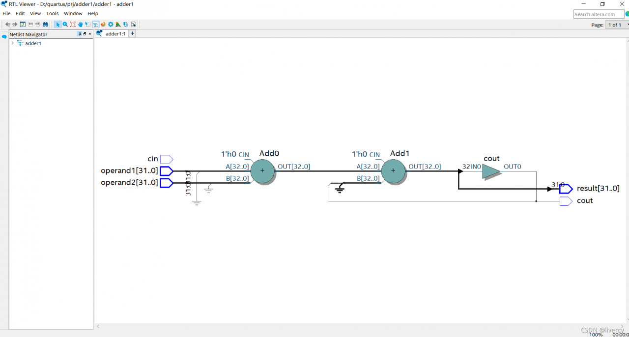
Codes:
module adder(
input [31:0] operand1,
input [31:0] operand2,
input cin,
output [31:0] result,
output cout
);
assign {cout,result} = operand1 + operand2 + cout;
endmodule
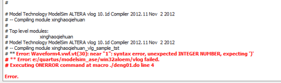
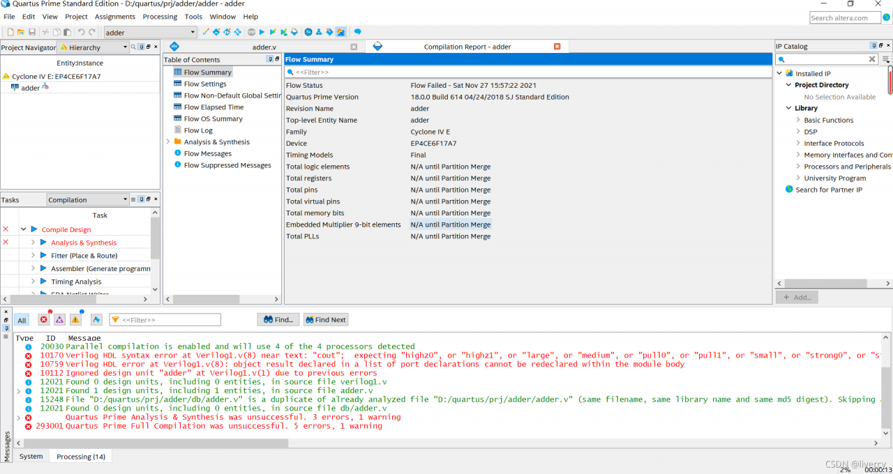
Error Messages:
Error (10170): Verilog HDL syntax error at Verilog1.v(8) near text: “cout”; expecting “highz0”, or “highz1”, or “large”, or “medium”, or “pull0”, or “pull1”, or “small”, or “strong0”, or “strong1”, or “supply0”, or “weak0”, or “weak1”. Check for and fix any syntax errors that appear immediately before or at the specified keyword. The Intel FPGA Knowledge Database contains many articles with specific details on how to resolve this error. Visit the Knowledge Database at https://www.altera.com/support/support-resources/knowledge-base/search.html and search for this specific error message number.
Error (10759): Verilog HDL error at Verilog1.v(8): object result declared in a list of port declarations cannot be redeclared within the module body
Error (10112): Ignored design unit “adder” at Verilog1.v(1) due to previous errors
Error: Quartus Prime Analysis & Synthesis was unsuccessful. 3 errors, 1 warning
Error: Peak virtual memory: 4702 megabytes
Error: Processing ended: Sat Nov 27 15:57:22 2021
Error: Elapsed time: 00:00:12
Error: Total CPU time (on all processors): 00:00:27
Error (293001): Quartus Prime Full Compilation was unsuccessful. 5 errors, 1 warning
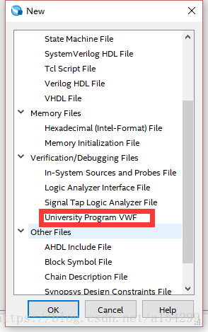
Solution:
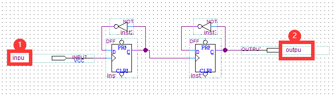
Select the option in the red box.
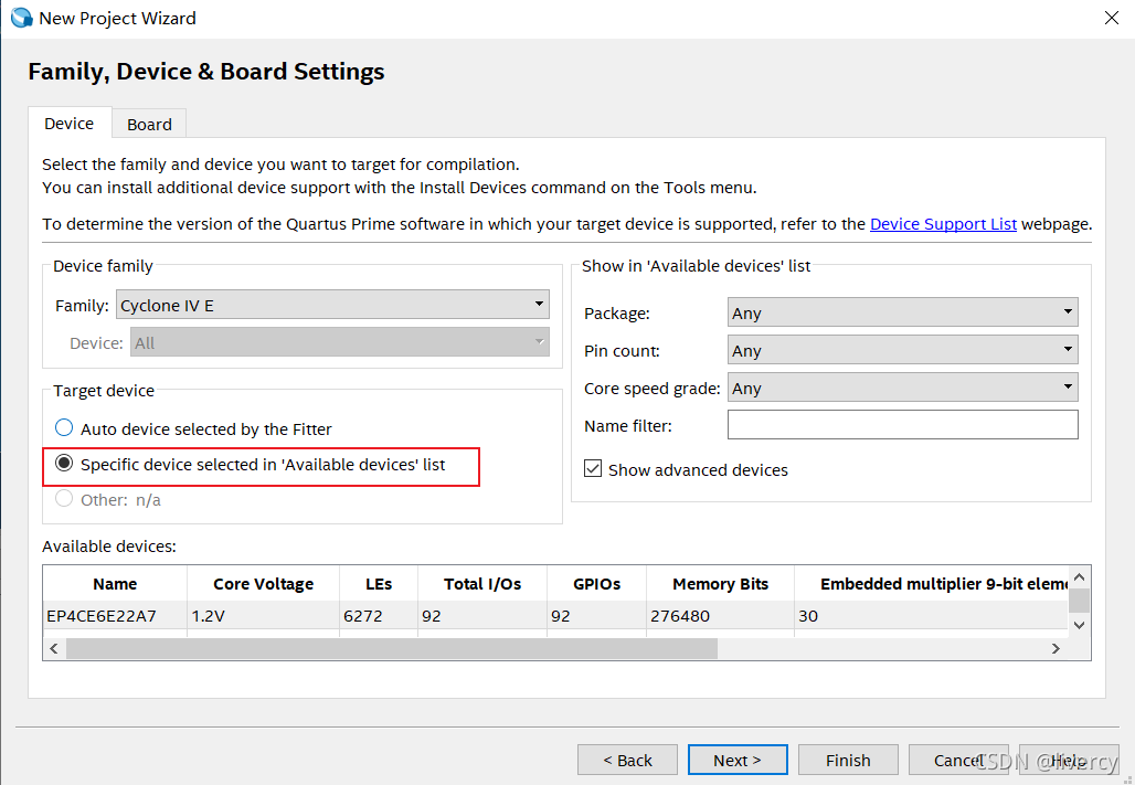
Done!