The Keil version is v5.25.30.0
the Downloader is st-link
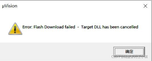
1. As shown in the figure below, Keil prompts error: Flash download failed – target DLL has been cancelled
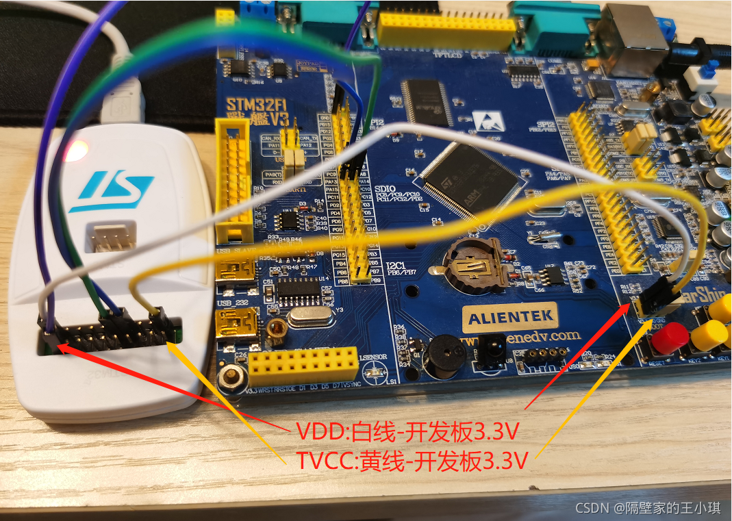
2. The reason is that the TVCC of st-link in the figure below is not connected to the 3.3V of the circuit board
as shown in the figure below. When the yellow line is connected, it can be downloaded normally. If the yellow line is not connected to stlink, The target DLL has been cancelled error will appear
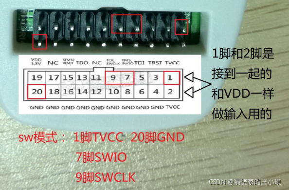
3. Discuss the difference between Vdd and TVCC in stlink
as shown in the figure below, TVCC is pin 1.2. When stlink is plugged in USB, TVCC has no 3.3V output
VDD is pin 19. When stlink is plugged in USB, VDD has 3.3V output

when downloading the program in SW mode:
TVCC must receive 3.3V to download successfully, otherwise an error will be reported: Flash download failed – target DLL has been cancelled
VDD is not connected
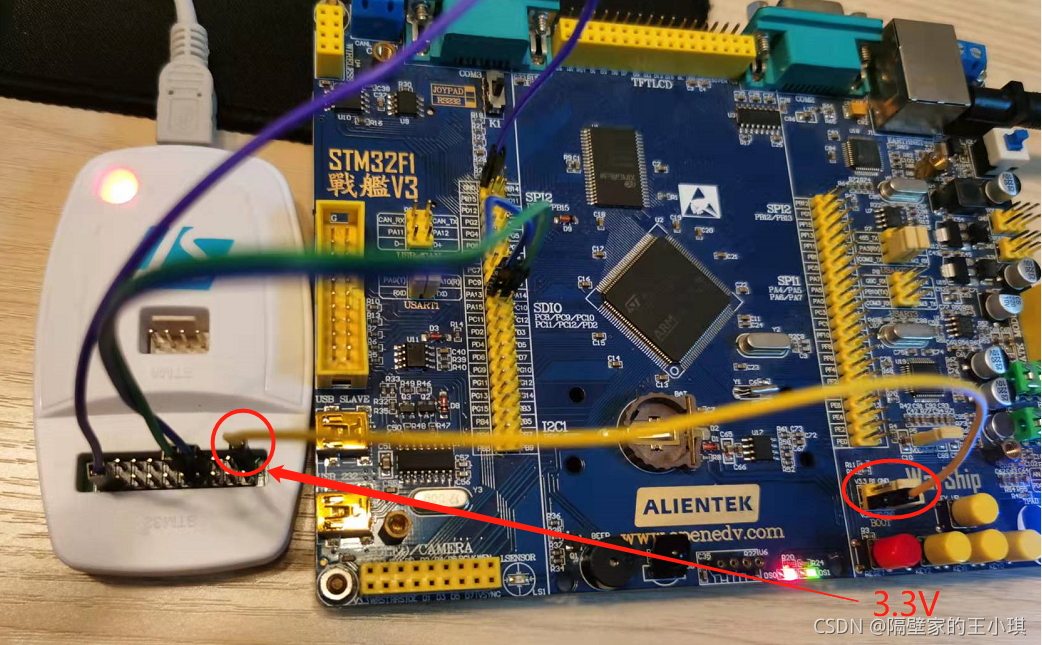
So can VDD be connected to TVCC to power up the single chip microcomputer?I tried. It is feasible in theory, but I generally don’t do so, because the 3.3V driving ability is not strong
I test with the board of the punctual atomic warship. When VDD is connected to TVCC, both Vdd and TVCC will be pulled to about 2V, and keil can also successfully download the code. As shown in the figure below, VDD gives a voltage of 3.3V to the MCU through the white line, and then to TVCC through the yellow line. However, the LED will not be lit. Personally, I think the voltage is too low
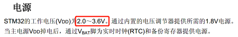
Looking through the manual of STM32, you can see that the working voltage of STM32 is 2v-3.6v, so Vdd and TVCC are two or more volts, which can also make the STM32 program download successful
to sum up:
1. TVCC itself has no voltage. When downloading the program, it needs to be connected to 3.3V of the circuit board
2. VDD can supply power to the MCU to download the program. At the same time, if the power is supplied on the circuit board or separately, VDD should not be connected to the development board to avoid the conflict between the two 3.3V. So it can be described by one word, but it’s not necessary. VDD is just a foot that doesn’t exist. Don’t use it
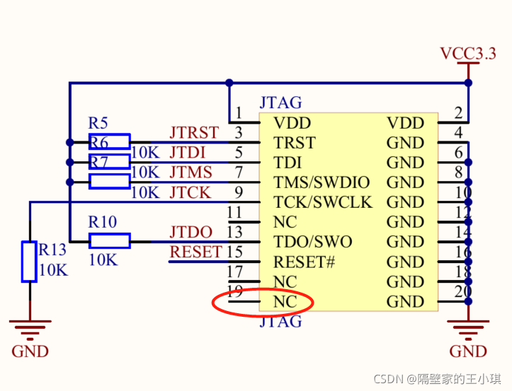
PS: the standard JTAG interface is attached. It can be seen that the 19 pin is not connected. I don’t quite understand why stlink wants to output the 19 pin to 3.3V as VDD
Read More:
- 【Keil】Error: Flash Download failed – Target DLL has been cancelled
- Error: Flash download failed – “cortex-m4″“
- VMware (3): MacOS download software prompts “failed to complete the operation. ( com.apple.commerce . client error 500.) “
- Mac running nltk.download () prompt certificate verity failed
- Hbuildx syntax prompt library download failed
- Bug: unable to download source code in idea, error cannot download sources sources not found for:XXX
- Gd32e303zet6 download prompt error
- NPM modify download dependency (modify global download and cache path)
- Ajax can’t download file to browser
- OpenGL program running prompt glut32.dll missing problem
- Failed to download resource “expect_bottle_manifest“
- 0028opengl program running prompt glut32.dll missing one of the solutions
- Visual studio 2017, OpenGL program running prompt glut32.dll missing solution
- Failed to download package files error after re installing Ubuntu
- Failed to download when creating Vue project, solution
- Some index files failed to download. They have been ignored, or old ones used instead
- This program cannot be started because vcruntime140 is missing from your computer_ 1.dll。 Try to install the program again to solve the problem.
- Win10 (1703) app store download app prompt error code 0x80d0000a
- NIOS II – Eclipse – ERROR – ” DownLoad elf failed ” – Verify failed between address ….
- Error analysis of veeam backup: failed to create NFC download stream