Category Archives: How to Fix

Common problems and basic concept knowledge of OpenGL

OpenGL FAQ and basic concept knowledge (continuously updated!!)
1. The concept of matrix in OpenGL, what is Model,View,Project?
We know the World in the OpenGL Matrix (World Matrix)/View Matrix (the View Matrix and Projection Matrix (the Projection matirx)
in the Model: the Matrix determine the World coordinates of a unified, mainly aimed at the Model of translation, rotation, scaling, shear, and other functions, is the Model from local space into World space.

Projection matrix is the part of the scene that we can see, with the camera/observer position and so on (set mouse movement, scroll wheel, etc.), and converts all world coordinates to View coordinates.
2. Scheduling between CPU and GPU in OpenGL

OpenGL program involves two types of processing unit CPU and GPU.
engl main program has CPU call to run, image processing part through GLSL to GPU execution.
Data transfer between CPU and GPU is divided into three steps:
1. First use the built-in OpenGL function to generate an ID number
2. According to the need for the ID number of memory types of binding, binding to be used in the receiving system after the completion of the GPU memory of the data in the “identifier” will be ready,
3. This part of memory is initialized. The initialized content is from the system memory, and this part of function is completed by the glBufferData function. After the data is submitted to the GPU dedicated memory, it is necessary to allocate the data according to the application scenarios, such as some data as vertices, some as colors, some for illumination control and so on
In addition, due to the high parallel structure of GPUs, all GPUs have high computational efficiency in processing graphics and complex algorithms. Most of the CPU area is controllers and registers, while GPUs have more ALUs, logical operational units for data processing, rather than data caching and flow control.
The concept of buffers in OpenGL
[1] Frame Buffer: A frame buffer is a combination of the following buffers. Using frame buffers allows you to render your scene into a different frame buffer, which allows you to create mirrors in the scene, or create cool effects that store data for the display.
[2] Color Buffer: Stores the color of all fragments: that is, the effect of visual output.
[3] Depth Buffer: determines which facets are occluded according to the Z value of the buffer. Automatically generated by GLFW.
[4] stencil buffer: Similar to depth testing, the template value is compared to the default value to determine whether to discard the fragment.
Data is processed in OpenGL in the following order: vertex shader – fragment shader – template test – depth test
The concept of depth testing
1. What is depth?

OpenGL will have a special area for storing Z value (the Z value on each pixel), which is the depth cache.
2. Depth Buffer Function?
In general, when we draw a graph, the later drawing overrides the previous graph, and the general drawing order is drawn from the back to the front. So there is a performance problem with the “covered part”, where the first part is covered, and all you see is the top part of the module and the bottom part of the covered part is not meaningful!
depth test appears to solve the covering problem
nction: when the depth test is turned on, the Z value will be checked. The same area close to the observer will be drawn, and other covered areas will not be drawn, regardless of the order of drawing.
3. How to use the deep cache test?

enable (GL_DEPTH_TEST);
glEnable(GL_DEPTH_TEST);
in the above code open depth test by default, the Z value under the condition of small will be overwritten
If the observer is in the positive direction of the Z axis, the Z value is close to the observer
If the observer is in the negative direction of the z-axis, the smaller z-value is closer to the observer

How to solve the conflict problem caused by the same depth value (same Z value)?
The first method: in the second drawing the same Z value, the tiny offset cover problems
note: must be very careful to ensure that the Z value of the gap, or like a refrigerator on the refrigerator as suspended risk
The second method is to sample the GLPolygonOffset function so that the depth value of the fragment can be adjusted so that the depth value is offset without creating a suspended emphasis

Some problems in OpenGL

[size=large] I recently tried to write some OpenGL programs. I found some small problems, and I’m going to record them. If I understand them in the future, I will look back and see that I have witnessed some growth.

> First, the context. In fact, we know color coloring, can be divided into direct use color glColor4f(); You can also use a vertex array to color glColorPointer(); To color. However, if this property is enabled: gl.glEnable(gl10.gl_texture_2d); Will invalidate the color of. So, if enabled before, disable this property before painting, and then paint in the color. As a result, the problem is that texture and color have no co-existence, meaning that color never affects texture. However, I think this is not the case. Is the understanding of mixing not enough or something?I hope to find the answer to this question in the follow-up study.

and, before the use of an array, must open his first, such as color array, using the former to gl. GlEnableClientState (GL10. GL_COLOR_ARRAY);

Otherwise it’s white. Checking up is also more troublesome.

[/size]

Visual studio 2017, OpenGL program running prompt glut32.dll missing solution

From: http://blog.csdn.net/liufeng520/article/details/8064170
My question is exactly the same as above, so make a note of it for later review and reference.
Today debug OpenGl source program, compiled through, but a running tips, computer lost glut32. DLL files, not depressed, search under the Internet provide most of the practice are more, copying the file to download this file to C: \ WINDOWS \ system in 32, but did so after found that still doesn’t work, after a long afternoon, suddenly realized that may be about my new WINDOWS 7 system, but also for loading is 64 – bit, then, Try to copy this glut32.dll to your SysWOW64 folder in C:\ Windows, and it will all be OK. Here’s a special note to remind everyone who installed Windows 7 and VC ++ 6.0 to pay attention to it.
PS: When I just started to contact OpenGL, I will inevitably encounter some problems. These problems may have nothing to do with the program, but some compilation environment Settings and header file installation. In particular, I have arranged them as follows:
(1) Copy gult32.dll, Glut. DLL to Windows system system32(if Windows 7 is a 64-bit operating system, it is in C:\ Windows SysWOW64 file)
(2) Copy gult32.lib, Glut. lib to VC lib directory
(3) Copy ULT. H to include\GL of VC

OpenGL learning — problems encountered in compiling OpenGL program for the first time

The first time you compile and run an OpenGL program, you run into a bug that makes you crazy.
It looks like this:

A lot of search on the Internet, found that this is the first time to compile OpenGL program will meet the error. The solution is as simple as the #include< gl/glut.h> Preface it with a code like this:

Also note that the order of the code must be in #include< gl/glut.h> Before, can not error, otherwise still can not pass.

Learning notes of OpenGL — blending

Note: This document is only about the main points and some of my own new ideas. It is not a tutorial. For a tutorial, see the OpenGlLearn article.

Blending can make the object transparent.
Transparency can be achieved in two ways:
‘1’ means discard part of the fragments. In this case, there are no translucent fragments.
Two is really mixing. The current segment and the target segment are weighted according to a certain formula.
【 1 】

#version 330 core
out vec4 FragColor;

in vec2 TexCoords;

uniform sampler2D texture1;

void main()
{             
    vec4 texColor = texture(texture1, TexCoords);
    if(texColor.a < 0.1)
        discard;
    FragColor = texColor;
}

A segment that is always bright, discarded, but this if will branch logically, so that’s the efficiency…

Set the surround texture to GL_CLAMP_TO_EDGE to slightly improve the visual effect.

[2] Mixing
Enable the blend: glEnable(GL_BLEND);

GLBLENDFUNC (GL_SRC_ALPHA, GL_ONE_MINUS_SRC_ALPHA);
So source alpha and 1-source alpha
Here glblendFunc is the mixed operation setup function.
GlblendFunction Separate is a bit more subtle and allows you to set the action function for both color and Alpha separately.

Both set the source and target, how to handle RGB and alpha values.

GlblEndequation can be used to set the blending operator. In fact, the most common one is GL_FUNC_ADD


This function sets the formula to use to handle the alpha and RGB values.

The principle of mixing:
If you’ve already drawn something before mixing it (even a skybox is OK), what about wool?
When blending, the object to be drawn is the Source, and the object already drawn is the Target.
When blending, you don’t have to change anything in your Shader. The pieces will blend themselves with the drawn pieces according to the blending formula and numerical rules. Unity uses the syntax of ShaderLab to set up these functions.

An explanation of a previously encountered problem:
A few months ago, I had an issue with WorldCreatorPro where the trees would become translucent slices when I used Slice LOD instead of SpeedTree, which was far away from the map. At this point, the translucent area hides the terrain behind.

Now it’s easy to explain. Borrowing the graph from the Learnopengl author:


Look at the hoop:
If the previous diagram is drawn first, the transparent pixels here will also be written to the ZBuffer, since the Z-Buffer ignores Alpha.
When the object behind is drawn (whether it is transparent or not, as long as it is farther away from the object in front) the z-test fails and the corresponding pixel is discarded.

Conclusion: When Z-buffer and Blending theory are used together, it is necessary to draw distant objects first and then close ones to ensure no mistakes.
The trees we used before, even if we could sort them, it would be a terrible overhead to arrange thousands of trees in order every frame and then render them. So we could just switch to SpeedTree and use model LOD instead of map LOD, although it would be really cheap.

Method: How to use Blending correctly.

    Draw all opaque objects first. Sort all transparent objects. Draw all transparent objects in order (from far forward). In particular, you can sort by distance insertion, drawing far away first, and then drawing near.

Learning notes — opengl01

 
The first lesson
1.1 Simple OpenGL program contains:
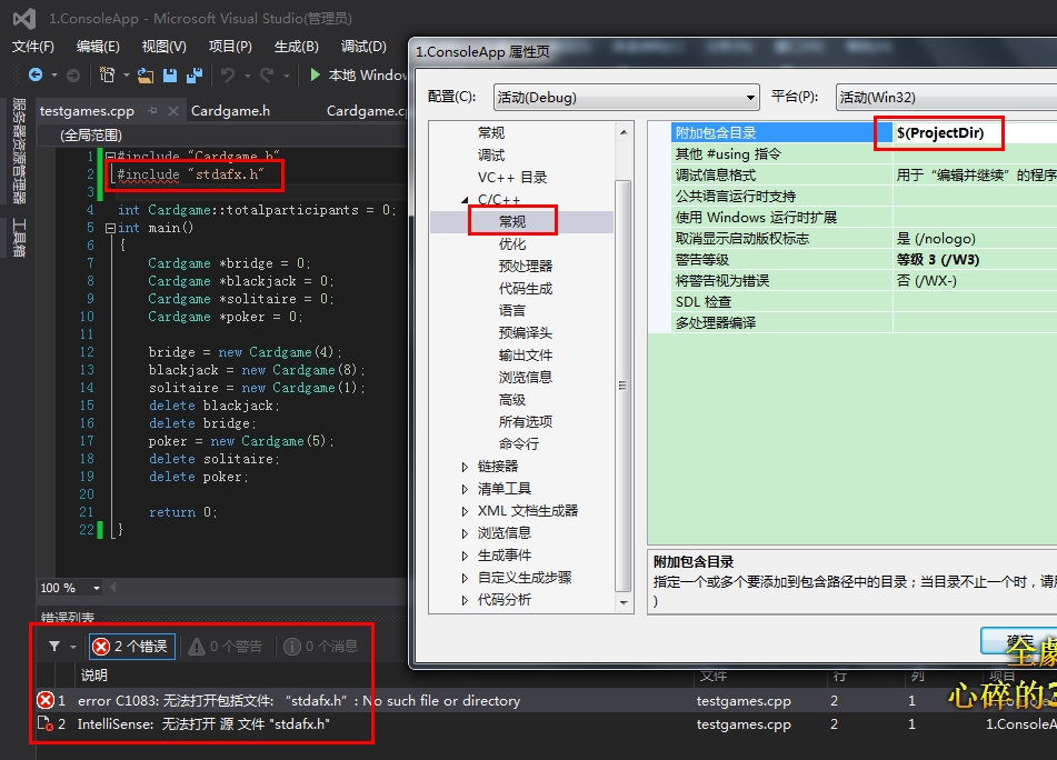
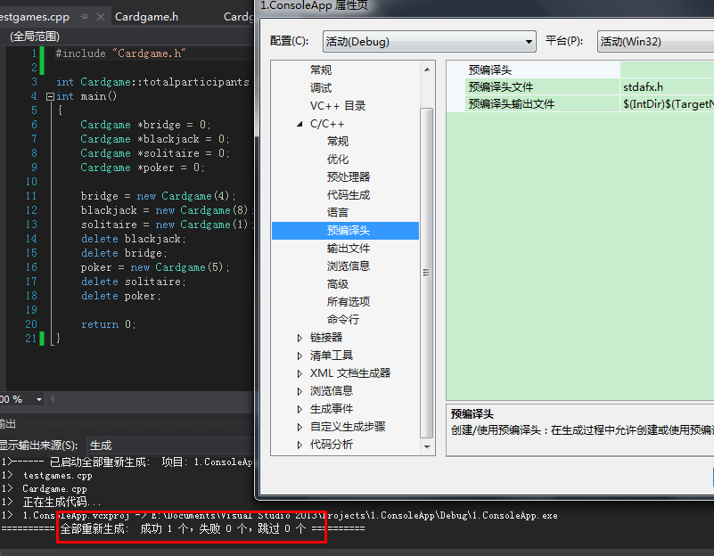
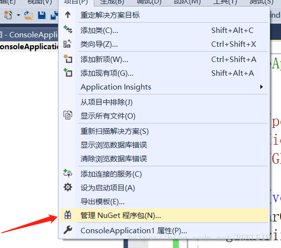
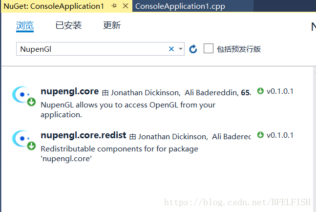
First, you need to include the header file #include <; GL/glut.h> So this is the header file for GLUT. OpenGL programs typically include <; GL/gl.h> And & lt; GL/glu.h> , but both files are automatically included in the GLUT header file and do not need to be included again.   The functions that begin with GLUT are all functions provided by the GLUT toolkit. Here are some of the functions used: Glutinit initializes GLUT. This function must be called once before another GLUT is used. Glutinit (& Arg C, Arg V. 2, GLUTINITDISPLAYMODE, set the display mode, where GLUT_RGB means to use the RGB color, and GLUT_INDEX (means to use the index color). GLUT_single means to use a single buffer, as does GLUT_DOUBLE (to use a double buffer). GlutinitWindowPosition, which is simple, sets the position of the window on the screen. 4, GlutinitWindowSize, this is also easy, set the window size. 5, GlutCreateWindow, create a window based on the information set above. Parameters will be used as the title of the window. Note: The window is not immediately displayed on the screen after it is created. You need to call glutMainLoop to see the window. 6. GlutdisplayFunc, which sets a function that will be called when a drawing is needed. (This statement is not accurate, but the accurate statement may not be easy for beginners to understand, so say for the time being). 7. GlutMainLoop, which runs a message loop. (This may not be obvious to beginners, but for now it is enough to know that this function displays a window and waits for the window to close before returning.)   All the functions that start with GL are standard OpenGL functions, and the ones that are used are described below. 1, Glclear. GL_Color_BUFFER_BIT clears the color, and glClear clears other things, but I won't cover them here. 2, Glrectf, draw a rectangle. The four parameters represent the horizontal and vertical coordinates of the two points located on the diagonal. Glflush ensures that previous OpenGL commands are executed immediately (rather than having them wait in the buffer). It works similarly to fflush(stdout).   The second lesson 2.1 Draw simple geometric shapes Dots: Dots in OpenGL will be drawn as individual pixels Straight lines: OpenGL's concept of a "line" is close to the mathematical concept of a "line segment," which can be defined by two endpoints. 
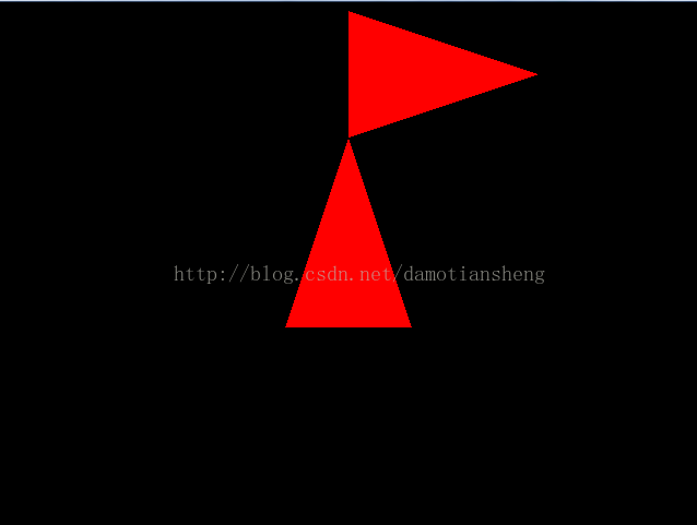
Polygon: A polygon must be a "convex polygon" (defined as: any two points in a polygon are within the polygon, from which it can also be deduced that a convex polygon cannot be hollow), usually triangular By using points, lines and polygons, you can combine various geometric figures   2.2 Specify vertices OpenGL provides a number of functions. They all start with glVertex, followed by a number and one or two letters. Such as: GLVERTEX2D GLVERTEX2F GLVERTEX3F GLVERTEX3FV and so on. The number means the number of arguments, 2 means there are two arguments, 3 means three, and 4 means four. Letters parameter type, s 16-bit integers (due to the type defined as GLshort OpenGL), I said a 32-bit integer (OpenGL in this type is defined as the GLint and GLsizei), f is a 32-bit floating point Numbers (due to the type defined as GLfloat OpenGL and GLclampf), d said 64 floating point Numbers (due to the type defined as GLdouble OpenGL and GLclampd). V indicates that several parameters will be passed using Pointers   2.3 Start drawing OpenGL requires that the command specifying the vertex be included after glBegin and before glEnd (otherwise the specified vertex will be ignored). GlBegin is left to indicate how to use these points. Such as: glBegin(GL_POINTS); GlVertex2f (0.0 0.0 f, f); GlVertex2f (0.0 0.5 f, f); glEnd(); Then these two points will be drawn separately. If you replace GL_POINTS with GL_LINES, then the two points will be considered to be the two endpoints of the line, and OpenGL will draw a line. You can also specify more vertices and then draw more complex shapes. GL_POINTS, GL_LINES, GL_LINE_STRIP, GL_LINE_LOOP, GL_TRIANGLES, GL_TRIANGLE_STRIP, GL_TRIANGLE_FAN, etc. (See Figure 1) The third class 3.1 about the point Point size: Default value is 1.0F, function prototype void glpointSize (GLFloat Size); Example: void myDisplay(void) { glClear(GL_COLOR_BUFFER_BIT); GlPointSize (5.0 f); GlBegin (GL_POINTS); ... GlEnd (); glFlush(); } 3.2 About Straight Lines 3.2.1 Line width Function prototype void gllineWidth (glFloat Width); The usage is similar to glpointSize. 3.2.2 dotted line First, use glEnable(GL_LINE_STIPPLE); To start the dotted line mode (use glDisable(GL_LINE_STIPPLE) to turn it off). Then, use glLineStipple to set the style of the dotted line. void glLineStipple(GLint factor, GLushort pattern); Pattern is a sequence of length 16 composed of 1 and 0. Viewed from the lowest position, if it is 1, then factor points that should be drawn next on the line will be drawn as solid. If 0, then factor points that should be drawn next on the line will be drawn as virtual. 3.3 About polygons 3.3.1 Both sides of polygons and their drawing methods 
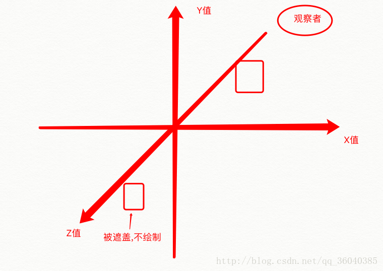
Although we haven't really used 3D coordinates to draw a picture yet, it is necessary to establish some 3D concepts. In three dimensions, a polygon has two faces. Each face can be drawn in a different way: fill, draw only edges, and draw only vertices, with fill being the default. You can set the two faces in different ways. glPolygonMode(GL_FRONT, GL_FILL); // Set front to fill mode glPolygonMode(GL_BACK, GL_LINE); GlPolygonMode (GL_FRONT_AND_BACK, GL_POINT); glPolygonMode(gl_front, GL_POINT); // Set both sides to vertices 3.3.2 rainfall distribution on 10-12 inversion The convention is that the face whose vertices appear counterclockwise on the screen is "heads" and the other face is "tails". Common surfaces in life can usually be represented with such "heads" and "tails" as "reasonable". But there are some surfaces that are special. For example, a "Maibius strip" can be represented with either all "heads" or all "tails". You can exchange the concepts of "heads" and "tails" through the glFrontFace function. glFrontFace(GL_CCW); // Set the CCW direction to "Front", CCW is Counterclockwise Glfrontface (GL_CW); // Set the CW direction to "Front", CW is ClockWise * There is routine openGL4 
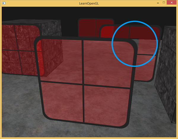
3.3.3 Remove polygonal surfaces In three dimensional space, a polygon has two faces, but we can't see the polygons on the back, and some of the polygons are on the front, but are obscured by other polygons. Treating invisible polygons the same as visible polygons will definitely reduce the efficiency of our graphics processing. At times like this, you can cut out unnecessary surfaces. First, use glEnable(GL_CULL_FACE); To enable culling (disable using glDisable(GL_CULL_FACE)), then use glCullFace to cull. The parameter of glCullFace can be GL_FRONT, GL_BACK, or GL_FRONT_AND_BACK, which are polygons that remove the front, back, and back sides, respectively. Note: the cull function only affects polygons, not points and lines. For example, with glCullFace(GL_FRONT_AND_BACK), all polygons are removed so that only points and lines are visible. 3.3.4 Hollow out polygon Straight lines can be drawn as dotted lines, while polygons can be hollowed out. First, use glEnable(GL_POLYGON_STIPPLE); To start the hollowout mode (which can be turned off with glDisable(GL_POLYGON_STIPPLE)). Then, use glPolygonStipple to set the hollow out style. void glPolygonStipple(const GLubyte *mask); The mask parameter points to a space of 128 bytes, which indicates how a 32 by 32 rectangle should be hollow out. Where: The first byte indicates whether the 8 pixels at the bottom left are hollow (1 means no hollow, showing the pixel; 0 indicates hollowout, showing the color behind it), and the last byte indicates whether the top right eight pixels are hollowout or not. If such data is saved as a picture and edited with a special tool, it is obviously much more convenient. Here's how to do it. First, create a new image using the Windows Brush program and name it mask.bmp. Make sure to save it with "Monochrome Bitmap" selected. In "Image" -> In the Properties dialog box, set the height and width of the image to 32. Look at the picture with a magnifying glass and edit it. Black corresponds to binary zero (hollow out), white corresponds to binary one (no hollow out), after editing saved. You can then use the following code to get the Mask array.
static GLubyte Mask[128];
FILE *fp; fp = fopen(“mask.bmp”, “rb”);
if( ! fp ) exit(0);
// Move the file pointer to this position so that reading sizeof(Mask) will encounter the end of the file
// Note that -(int)sizeof(Mask) is not a good way to write it, but it does work here, right
If (fseek(fp, -(int)sizeof(Mask), SEEK_END) exit(0); if(fseek(fp, -(int)sizeof(Mask), SEEK_END) exit(0);
// Read the sizeof(Mask) bytes into the Mask
if( ! fread(Mask, sizeof(Mask), 1, fp) )
exit(0);
fclose(fp);
 
Edit an image as a mask, and use the above method to get the array of masks. After running, observe the effect. Note: The factor factor can be set when drawing a dashed line, but the factor factor cannot be set when drawing a hollow polygon. Please use the mouse to change the size of the window, observe the change of the hollowout effect.
* There is routine openGL5

Solution of unable to open source file “StdAfx. H” in vs2013 / 2012

Unable to open source file “stdafx.h”. Unable to open source file “stdafx.
As shown in figure:

Baidu, for VS2010 there are such methods can be solved:
Expand C/C++ in Project Properties, select General, and add “$(projectDir)” in the Additional Includes directory.

As you can see, it doesn’t work at all in my VS2013.

And it worked:
The precompiled header file is its own, I think VS2013/2012 includes “stdafx.h” by default, so I don’t have to write it again

OpenGL Usage Summary (including problems encountered and solutions)


glMatrixMode(gl_modelView);
// Reset the model observation matrix.
glLoadIdentity ();
//
selection model observation matrix gluLookAt (3.0 f to 2.5 f to 5.0 f to 0.0 f to 0.0 f to 0.0 f to 0.0 f to 1.0 f to 0.0 f);
Note: Be sure to call glLoIdentity to reset the currently specified matrix to the identity matrix before calling gluLookAt.

br> <>>

2. When you do texture mapping, you find that the texture and color are mixed.
To mask the effects of GLColor3F, simply add:
GlColor3f (1.0, 1.0, 1.0);
or add: glTexenvi (GL_TEXTURE_ENV, GL_TEXTURE_ENV_MODE, GL_REPLACE);

glgentextures6, &
glgentextures6, & texture[i]);
glBindTexture (GL_TEXTURE_2D, texture [I]);
glutInit(&
glutInit)
glutInit(&
glutInit)
glutInit(&
glutInit)
glutInit(& argc, argv);
glutInitDisplayMode(GLUT_DEPTH | GLUT_DOUBLE | GLUT_RGBA);
glutInitWindowPosition (0, 0);
glutInitWindowSize(800, 600);
glutCreateWindow(“Wander”);
wander.load_GL_textures1();
=
=
=
=
=
=
=

1.
GlFrontFace (GL_CCW); // Specifies counterclockwise as the front
GlCullFace (GL_BACK); // Make the back side invisible
GlEnable (GL_CULL_FACE);
 
2.
// Pyramid objects are not mapped, so you should not enable texture mapping, otherwise you will not see the object
//glEnable(GL_TEXTURE_2D);
// Enable texture mapping, enable texture mapping before the object to be mapped, disable texture mapping after the object is drawn, if enabled before all the objects to be drawn, the object will not be seen if GLTextCoord2f is not used
 
3.
GlClear (GL_COLOR_BUFFER_BIT | GL_DEPTH_BUFFER_BIT); // Clear Screen And Depth Buffer
GlMatrixMode (GL_MODELVIEW); // Set the Model View Matrix to determine the position of an object in 3D space
GlLoadIdentity (); //M=I; I is the identity matrix
 
GlColor3f (1.0f, 0.0f, 0.0f);
GlBegin (GL_TRIANGLES);
GlVertex3f (0.0 f, f, 2.0 0.0 f);
GlVertex3f (0.0-1.0 f to 1.0 f, f);
GlVertex3f (0.0 1.0 f to 1.0 f, f);
GlEnd ();
 
GlTranslatef (0.0 1.0 f, 3.0 f, f); // If x is shifted by 1, y is shifted by 3, and z is guaranteed to remain the same, the corresponding matrix is:
// After translation, M=M*K=I*K,K = x shifted by 1, y shifted by 3, z guaranteed invariant translation matrix
// GlRotatef (90.0F, 0.0F, 0.0F, 1.0F); // Rotate 90 degrees counterclockwise
GlRotatef (-90.0F, 0.0F, 0.0F, 1.0F); // Rotate 90 degrees clockwise
// After rotation, M=M*R=K*R,R is the corresponding selection matrix above
/ *
K =
1 0 0 1
0 1 0 3
1 0 0 0
0 0 0 to 1
 
The rotation matrix of @ degrees about the z axis, R is equal to
Cos @ – sin @ 0 0
Sin @ cos @ 0 0
1 0 0 0
0 0 0 to 1
Substitute @=-90 to get:
1 0 0 0
1 0 0 0
1 0 0 0
0 0 0 to 1
Have to M =
1 0 0 1
1 0 0. 3
1 0 0 0
0 0 0 to 1
And then multiply the homogeneous coordinates of the following three coordinates right by M to get the final coordinates,
P ‘= MP, P for the original coordinates of the corresponding homogeneous coordinates, such as the first point (0.0, 2.0, 0.0) of homogeneous coordinates (0.0, 2.0, 0.0, 1.0) for
The final three coordinate positions are:
   
A1 =
3
3
0
1
 
A2 =
0
4
0
1
 
A3 =
0
2
0
1
Finally, draw the triangle corresponding to the three points
* /
 
GlColor3f (0.0 1.0 f, 0.0 f, f);
GlBegin (GL_TRIANGLES);
GlVertex3f (0.0 f, f, 2.0 0.0 f);
GlVertex3f (0.0-1.0 f to 1.0 f, f);
GlVertex3f (0.0 1.0 f to 1.0 f, f);
GlEnd ();
The results are as follows:

Note: OpenGL uses right multiplication
 
 
4. The maximum size of texture map should not exceed 256*256, preferably BMP image
The width and height of the image must be 2 to the power of n; Width and height must be 64 pixels minimum; And for compatibility reasons, the width and height of the image should not exceed 256 pixels. If the width and height of your raw material is not 64,128,256 pixels, use image processing software to resize the image.
I mentioned earlier that there are ways around OpenGL’s restrictions on texture width and height — 64, 128, 256, etc. The solution is gluBuild2DMipmaps. As I’ve found, you can use any bitmap to create a texture. OpenGL will automatically scale it to its normal size.
GluBuild2DMipmaps (GL_TEXTURE_2D, 3, TextureImage [0] – & gt; sizeX, TextureImage[0]-> sizeY, GL_RGB,GL_UNSIGNED_BYTE, TextureImage[0]-> data);
Note: It seems that only BMP images can be loaded, not other types of images
 
5.
/ *
The purpose is to reset the model observation matrix. If we call glTranslate directly without resetting, unexpected results will occur.
Because the axis has rotated, it’s probably not going in the direction you want. So we wanted to move the object left and right,
Depending on how much Angle you’ve rotated the axis, it might move up and down.
* /
   
6. Default viewpoint position:
The default viewpoint position is at the point (0,0,0) and the orientation is vertical into the screen (that is, negative z-axis).
When you draw an object, notice that you move the Z coordinate of the object back a few units and you see it.
Viewpoints are not changed by default, which can be done by setting the gllookAt function
 
7.
glGenTextures(3, & texture[0]); // The glGenTextures function returns n texture indexes based on the texture parameters,& Texture [0] stores the texture index
// Create Nearest filter map
/ *
GlBindTexture actually changes this state of OpenGL by telling OpenGL that any action done to the texture is done to the texture object to which it is bound,
For example, glBindTexture(GL_TEXTURE_2D,1) tells OpenGL that any Settings for 2D textures in the following code are for textures with index 1
* /
8. OpenGL does not set the color, directly draw four vertices, the resulting square, the default will be white;
9.

OpenGL program running prompt glut32.dll missing problem

Today debug OpenGl source program, compiled through, but a running tips, computer lost glut32. DLL files, not depressed, search under the Internet provide most of the practice are more, copying the file to download this file to C: \ WINDOWS \ system in 32, but did so after found that still doesn’t work, after a long afternoon, suddenly realized that may be about my new WINDOWS 7 system, but also for loading is 64 – bit, then, Try to copy this glut32.dll to your SysWOW64 folder in C:\ Windows, and it will all be OK. Here’s a special note to remind everyone who installed Windows 7 and VC ++ 6.0 to pay attention to it.
PS: When you first start to contact OpenGL, you will inevitably encounter some problems, these problems may have nothing to do with the program, just some compile environment Settings and the installation of header files, special sorting, as follows:
PS
(1) Copy gult32.dll, Glut. DLL to Windows system system32(if Windows 7 is a 64-bit operating system, it is in C:\ Windows SysWOW64 file)
(2) Copy gult32.lib, Glut. lib to VC lib directory
(3) Copy ULT. H to include\GL of VC

Two problems in OpenGL Programming

Error C2381: ‘exit’ : redefinition; error C2381: ‘exit’ : redefinition; error C2381: ‘exit’ : redefinition; __declspec (noreturn) differs. The solution to the problem is to include the #include< stdlib.h> On the # include & lt; gl\glut.h> Just before.

Error LNK2001: unresolved external symbol __imp____glutInitWithExit@12 Unresolved external symbol __imp____glutInitWithExit@12 Unresolved external symbol __imp____glutInitWithExit@12 Unresolved external symbol __imp____glutInitWithExit@12 Unresolved external symbol __imp____glutInitWithExit@12 Unresolved external symbol __imp____glutInitWithExit@12 Unresolved external symbol __imp____glutInitWithExit@12 Unresolved external symbol __imp____glutInitWithExit@12 Unresolved external symbol __imp____glutInitWithExit@12 Unresolved external symbol __imp____glutInitWithExit@12 Unresolved external symbol __imp____glutInitWithExit@12

#define GLUT_DISABLE_ATEXIT_HACK

It is estimated that the reason for the above problem is the repeated definition problem.

Configuring OpenGL in Visual Studio

This semester to learn the graphics, to use C ++ to write, which is mainly used OpenGL, so first of all, to configure OpenGL in Visual Studio
1. Create a new C ++ console application. File – & gt; New – & gt; project

2. Then click Item ->; Manage the NuGet package

3. Browse here, type NupenGL and search

4. After downloading and installing both of them, import the header file at the beginning of the source program, and you can use it