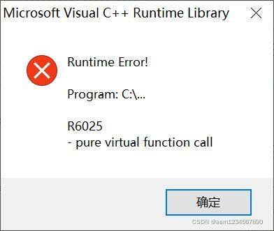
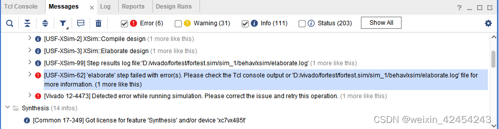
[USF-XSim-62] ‘elaborate’ step failed with error(s). Please check the Tcl console output . and
[Vivado 12-4473] Detected error while running simulation. Please correct the issue and retry this operation.
The problems are as follows:
Ways to find problems
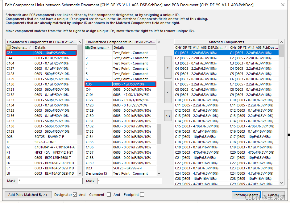
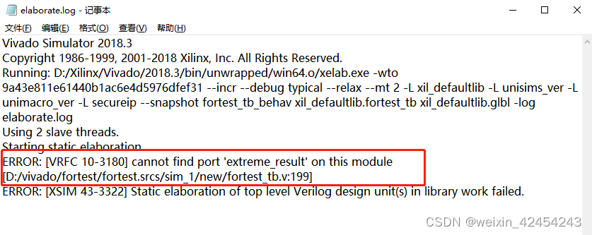
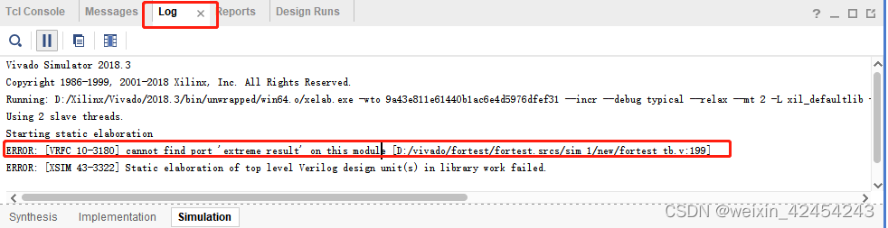
Method 1: messages in vivado cannot see detailed information, but after the error, the path of the log will be displayed. Open D:/vivado/fortest/fortest.sim/sim_1/behav/xsim/ elaboration.log, we can see error: [vrfc 10-3180] cannot find port ‘extreme_Result ‘on this module, modify the error
method 2: directly see the details in the log window in vivado, find the error, and then modify it
my error is that the port name of the instantiated function file in the simulation file is wrong.
Compare the size of two numbers of 8 bits
module extreme_8bit(
    extreme0,
    extreme1,
    DataSign,
    SubType,
    extreme_Result
    );

input [7:0]          extreme0;//vector operand 1 to participate in the most-valued comparison
input [7:0] extreme1;//vector operand 2 to participate in the most-valued comparison
input DataSign;//0: unsigned; 1: signed
input SubType;//0: find the maximum value max;1: find the minimum value min
output reg [7:0] extreme_Result;//the final result
reg extreme_c_carry;
wire carry;
wire [7:0] extreme_sum;
wire [7:0] temp_extreme0,temp_extreme1;//find the most value when the unsigned highest bit is the same, the virtual construction of the two numbers
reg [7:0] add_extreme0,add_extreme1;//enter the adder's operands for subtraction operations

Translated with www.DeepL.com/Translator (free version)
reg  [7:0]          min,max;
assign temp_extreme0={1'b1,extreme0[6:0]};
assign temp_extreme1={1'b0,extreme1[6:0]};


always @(*)begin
extreme_c_carry = 1'b1;
    if(DataSign==0)begin//0:unsigned
    {add_extreme0,add_extreme1} = {temp_extreme0,~temp_extreme1};
        if(SubType==0)begin//0: find the maximum value max, i.e. unsigned vector with same width integer subsumption max
            if(extreme0[7]! =extreme1[7]) begin // make sure the highest bit of the input data is inconsistent
                if(extreme0[7]==1) begin //extreme0>extreme1
                    max <= extreme0;
					extreme_Result <= max;
				end
				else begin //extreme0[7]==0;extreme1[7]==1;extreme0<extreme1
					max <= extreme1;
					extreme_Result <= max;
				end
            end
            else begin//extreme0[7]==extreme1[7] input data highest bit is the same, remove the highest bit to do the difference
                if(extreme_sum[7]==1)begin//extreme0>extreme1,when subtracting, the highest bit does not happen to be borrowed, the highest bit built 1 is still 1
				    max <= extreme0;
				    extreme_Result <= max;
				end
				else begin//extreme_sum[7]==0,extreme0<extreme1,,when subtracted, the highest bit is borrowed and the constructed 1 becomes 0
				    max <= extreme1;
				    extreme_Result <= max;
				end
            end
        end
        else begin//SubType==1,1:Find the minimum min, i.e., the minimum with unsigned vectors of the same width integer normalization
            if(extreme0[7]! =extreme1[7]) begin // Determine if the highest bit of the input data is inconsistent
                if(extreme0[7]==1) begin//extreme0>extreme1
					min <= extreme1;
					extreme_Result <= min;
				end
				else begin //extreme0[7]==0;extreme1[7]==1;extreme0<extreme1
                    min <= extreme0;
					extreme_Result <= min;
				end
            end
            else begin//extreme0[7]==extreme1[7]Input data highest bit is the same, remove the highest bit to do the difference
                if(extreme_sum[7]==1)begin//extreme0>extreme1,when subtracting, the highest bit does not happen to borrow, the highest bit built 1 is still 1
				    min <= extreme1;
					extreme_Result <= min;
				end
				else begin//extreme_sum[7]==0,extreme0<extreme1,,when subtracted, the highest bit is borrowed and the constructed 1 becomes 0
				    min <= extreme0;
					extreme_Result <= min;
				end
            end
        end
    end

    else begin//DataSign==1,1:with symbols
    {add_extreme0,add_extreme1} = {extreme0,~extreme1};
        if(SubType==0)begin//0: find the maximum value max, i.e. the signed vector with the same width integer subsumption max
            if(extreme0[7]! =extreme1[7])begin///heteroscedasticity of two numbers, the highest bit does not match the case to determine who is the largest integer
                if(extreme0[7]==1) begin//extreme0 is a negative number
					max <= extreme1;
					extreme_Result <= max;
				end
				else begin //extreme1 is a negative number
					max <= extreme0;
					extreme_Result <= max;
				end
            end
            else begin//The same number (with the same positive or negative) of two numbers, the highest bit of the same case to determine who is the largest integer
                if(extreme_sum[7]==1)begin//extreme0<extreme1,the result of subtraction is negative
				    max <= extreme1;
				    extreme_Result <= max;
				end
				else begin//extreme_sum[7]==0,extreme0>extreme1,the result of subtraction is positive
				    max <= extreme0;
				    extreme_Result <= max;
				end
            end
        end
        else begin//SubType==1,1:Find the minimum min, i.e., the signed vector with the same width integer normalized to the minimum
            if(extreme0[7]! =extreme1[7])begin///Determine who is the smallest integer if the two numbers with different signs and the highest bit do not match
                if(extreme0[7]==1) begin//extreme0 is a negative number
					min <= extreme0;
					extreme_Result <= min;
				end
				else begin //extreme1 is negative
					min <= extreme1;
					extreme_Result <= min;
				end
            end
            else begin//Two numbers with the same number (same positive or negative), the highest bit is the same to determine who is the smallest integer
                if(extreme_sum[7]==1)begin//extreme0<extreme1,the result of subtraction is negative
				    min <= extreme0;
				    extreme_Result <= min;
				end
				else begin//extreme_sum[7]==0,extreme0>extreme1,the result of subtraction is positive
				    min <= extreme0;
				    extreme_Result <= min;
				end
            end
        end
    end
end

RISCV_8BIT_REDADD extreme(
    .o_sum(extreme_sum),
    .o_cout(carry),
    .i_a(add_extreme0),
    .i_b(add_extreme1),
    .i_cin(extreme_c_carry)
);

endmodule
The multi bit width is divided into 8 bits to compare the size
module extreme_8bit_256(
    extreme0,
    extreme1,
    DataSign,
    SubType,
    extreme_temp,
    extreme_result256
    );
parameter M = 16; //VLEN = 256 ;
parameter N = 8; //SEW = 8 ;

input    [M-1:0]            extreme0;//The number of vector operands participating in the most-valued comparison1
input [M-1:0] extreme1;//vector operand 2 for the most-valued comparison
input [1:0] DataSign;//x0: unsigned; x1: signed
input [2:0] SubType;//0: find the maximum value max;1: find the minimum value min
output [M-1:0] extreme_temp;
output [N-1:0] extreme_result256;//the final result

extreme_8bit extreme_8bit_inst0(
    .extreme0(extreme0[N-1:0]),
    .extreme1(extreme1[N-1:0]),
    .DataSign(DataSign[0]),
    .SubType(DataSign[0]),
    .extreme_Result(extreme_temp[N-1:0])
    );

    genvar i;
    generate
    for(i = 0;i < 1;i = i + 1)begin
    extreme_8bit extreme_8bit_inst(
    .extreme0(extreme_temp[i*N+N-1:i*N]),
    .extreme1(extreme1[(i+1)*N+N-1:(i+1)*N]),
    .DataSign(DataSign[0]),
    .SubType(SubType[0]),
    .extreme_Result(extreme_temp[(i+1)*N+N-1:(i+1)*N])
    );

    assign extreme_result256[N-1:0] = extreme_temp[M-1:M-N];
    end

endgenerate

endmodule
Simulation file (the previous file reported an error because when the extreme_8bit_256 module was instantiated, the port extreme_result256 was incorrectly written as extreme_result, and all displays did not find the port extreme_result)
module fortest_tb(    );
parameter M = 16; //VLEN = 256 ;
parameter N = 8; //SEW = 8 ;

    reg    [M-1:0]         extreme0;
    reg    [M-1:0]         extreme1;
    reg    [1:0]           DataSign;//0:unsigned; 1: signed
    reg [2:0] SubType;//0: find the maximum value max;1: find the minimum value min
    wire   [M-1:0]         extreme_temp;
    wire   [N-1:0]         extreme_result;

    extreme_8bit_256 extreme_8bit_256_inst(
    .extreme0(extreme0),
    .extreme1(extreme1),
    .DataSign(DataSign),
    .SubType(SubType),
    .extreme_temp(extreme_temp),
    .extreme_result256(extreme_result)
    );

   initial  begin//DataSign;//x0:unsigned; x1: signed  SubType;//xx0:max;  xx1:min
   extreme0 = 16'b0;
   extreme1 = 16'b0;
   DataSign = 2'b00;
   SubType = 3'b000;
   #100
   SubType = 3'b000;
   extreme0 =  16'b1010_0001_0001_0111;
   extreme1 =  16'b0100_0111_1010_0001;
   #100
   SubType = 3'b001;
   extreme0 =  16'b1010_0001_0001_0111;
   extreme1 =  16'b0100_0111_1010_0001;
   #100
   DataSign = 2'b01;
   SubType = 3'b000;
   extreme0 =  16'b1010_0001_0001_0111;
   extreme1 =  16'b0100_0111_1010_0001;
   #100
   SubType = 3'b001;
   extreme0 =  16'b1010_0001_0001_0111;
   extreme1 =  16'b0100_0111_1010_0001;
   end
endmodule