Tag Archives: graphics

Several common methods of inserting pictures into latex documents

zz from: http://hepg.sdu.edu.cn/Service/tips/latex/latexfig.html#top & http://liqunsun.spaces.live.com/Blog/cns!285A08B51269F219!109.entry

Generally, latex only supports inserting EPS (encapsulated postscript) format graphics files directly, so we should try to get EPS format files before inserting pictures into latex documents.

all kinds of application software under UNIX can output the results in PS format, Most software can also output EPS format. If the software can only output PS format but not EPS format results, it can be converted to EPS format by ps2epsi command. Please refer to man ps2epsi’s instructions. If the image file format is bitmap graphics file, it can be converted to PS or EPS format file by display and convert tools of image magic package. See man page and man page for details

instructions

the output of windows software becomes PS / EPS file: please refer to the

“How to convert the output of software in Windows system into PS and EPS files”

Description in the column


Inserting pictures into latex documents is realized by using some latex graphics processing macro commands. Many macro commands support inserting EPS format graphics files into latex documents

(1) Using the macro command of includegraphics (graphicx package)

First of all, you need to add the following in the file description of latex document:

/usepackage{graphicx}

Then, it is quoted in the place where the image needs to be inserted:
/ includegraphics [height = height] {image file name} or / includegraphics [width = width] {image file name}
where “height” and “width” refer to the height and width of the image to be printed, and the unit must be given, which can be centimeter (CM) or inch (in), The image file name in the above command refers to the file name of the image file to be inserted. The image must be in EPS format

When inserting a picture with the macro command includegraphics of the graphicx package, you can also rotate the picture by:
/ includegraphics [height = height] [angle = rotation angle] {picture file name}

The inserted graphics are usually in EPS, PDF, JPG, PNG and other formats. Suppose the name is fig, and put it in the same directory of your tex document.
1. First add a sentence / usepackage {graphicx}
in the introduction area. 2. If you want to insert an inline graphic, you can directly use
/ includegraphics [width = 5in] {fig},
without adding a suffix.
This width is my most commonly used option, which can also be changed to other options.
3. If you want to insert floating graphics, use
/ begin {figure} [htbp]
/ centering / includgraphics [width = 3.5in] {fig}
/ caption {something} / label{ fig:1 }
/ end {figure}
4. For EPS graphics, the compilation process is latex, dvips, ps2pdf.
for PDF JPG PNG graphics, the compilation process is pdflatex

Use the include graphics macro command (graphics package) to:

It is troublesome to insert pictures with graphics package

(2) Using psfig macro command

First of all, you need to add the following in the file description of latex document:

/usepackage{psfig}

Then, it is quoted in the place where the picture needs to be inserted:
/ psfig {figure = picture file name, height = height} or / psfig {figure = picture file name, width = width}
where “height” and “width” refer to the height and width of the picture you want to print, and the unit bit must be given, which can be centimeter (CM) or inch (in), The image file name in the above command refers to the file name of the image file to be inserted. The image must be in EPS format

(3) use the epsfig macro command

The usage of epsfig macro command is exactly the same as that of psfig. The specific method is as follows:
first, add the following in the file description of latex document:

/usepackage{epsfig}

Then reference where you want to insert the image:

/ epsfig {figure = picture file name, height = height} or / epsfig {figure = picture file name, width = width}

The “height” and “width” refer to the height and width of the picture you want to print. The unit must be given, which can be centimeter (CM) or inch (in). The height and width can also be in the above format

The image file name in the above command refers to the file name of the image file to be inserted, and the image must be in EPS format


(4) Using EpsF macro command

The usage of EpsF macro command is as follows: first, add the following in the file description of latex document:

/usepackage{epsf}

Then, you can refer to:
/ epsfxsize = width / epsffile {image file name} or / epsfysize = height / epsffile {image file name} where you want to insert the image

The “height” and “width” refer to the height and width of the image to be printed. The unit must be given, which can be centimeter (CM) or inch (in). The height and width can also be given in the above format, so that the length width ratio of the original image can be changed. The image file name in the above command refers to the file name of the image file to be inserted, and the image must be in EPS format


(5) Latex? Picture control command, position control

Latex controls the position of the image by adding an exclamation point to ignore the “aesthetic” standard.
/ begin {figure} [! HTB]
/ usepackage {float}
/ begin {figure} [H]
insert it into the corresponding position of your code.

1, insert the side-by-side subgraph
/ usepackage {subfigure}

/ begin {figure} [H]
/ centering
/ subfigure [subfigurecaption] {
/ label{ Fig.sub .1}
/includegraphics[width=0.4/textwidth]{ figurename.eps }}
/subfigure[SubfigureCaption]{
/label{ Fig.sub .2}
/includegraphics[width=0.4/textwidth]{ figurename.eps }}
/caption{MainfigureCaption}
/label{ Fig.lable }
/ end {figure}

2, control the image position
if you don’t like latex to automatically arrange the image position, you can use the float package, and then
use / begin {figure} [H].
/ usepackage {float}
1, insert JPG image
in the command line environment, use the command:
ebb figure.jpg
Generating bounding box file figure.bb .
Use the following command:
/ includegraphics [width = 0.8/textwidth]{ figure.jpg }
PDF texify can be directly compiled into PDF file.
2, insert BMP image
there is no way to insert BMP image directly. The current method is to use
gimp to convert BMP into JPG, and then insert it according to the above method. When converting, do not use windows built-in painter, as the image quality is lost too much. With gimp or
fastone image viewer, the JPG quality is the highest, and the image quality is better.
3, insert JPG and EPS images at the same time
the insert command remains unchanged. When compiling, it uses latex and dvi2pdf, and the
images in both formats can be displayed.
Insert EPS picture
use / includegraphics [options] {file} command to insert EPS picture. The following is the simplest example:
/ documentclass {article}
/ usepackage {graphicx}% using the graphicx package
/ begin {document}
/ includegraphics{ file.eps }% insert the picture, insert it according to the original size of the picture
/ end {document}
note:
(1) EPS file and Tex file are placed in the same folder, which can be called only by the file name, without writing the path.
(2) Pdflatex cannot be used at compile time, an error will occur. Even if there are no mistakes, you can’t see the diagram. We should use latex compilation to generate DVI, and then dvi2ps, ps2pdf can see the figure.
Use [options] to specify the image size:
/ includegraphics [width = 3in]{ file.eps }
set the image width to 3 inches, and the image height will be automatically scaled.
/includegraphics[width=/testwidth]{ file.eps }
set the image width to the text width.
/includegraphics[width=0.8/textwidth]{ file.eps }
set the image width to 0.8 times the text width
/ includegraphics [width = / testwidth-2.0in]{ file.eps }
set the image width to be 2 inches less than the text width.
Use [options] to specify the image rotation angle:
/ includegraphics [angle = 270]{ file.eps }
rotate the image 270 degrees.
The two options are used at the same time, separated by commas:
/ includegraphics [width = / testwidth, angle = 270]{ file.eps }


A few useful articles on graph problems in latex

Graphics and Colour with LaTeX 

Online guide to illustration and color use in latex

Figure’ing and picture’ing latex (PS format)

The method of inserting PS graph and xfig graph into latex

Using imported graphics in latex 2e (PS format)

The illustration in latex is discussed in detail, including basic concepts, file formats and their mutual conversion, related software, etc. in addition, how to replace the characters in PS format pictures with latex format characters is also discussed, so as to solve the problem that some application software can not use special characters such as Greek alphabet and complex mathematical formula expressions

Latex maths and graphics (PS format)

It is mainly about the method of inserting pictures and formulas into latex.

this paper introduces the method of inserting pictures and formulas into latex

About Visio to EPS

Many people are used to drawing with Visio (including me), but Visio can’t export EPS format, so they have to rely on third-party software. Save it as *. EMF format through Visio, and then open it with OpenOffice draw to export it to EPS format. When exporting, you need to select the open image, so that after exporting EPS, only the content of *. EMF image will be included, and there will be no large blank. But the EPS image exported by this method will be out of shape, for example, the straight line will often be intermittent, and the “computer” shape I added in Visio will also have inexplicable shadows. Or maybe I didn’t set it up.

There is another better solution, the EPS file exported is perfect. In other words, the Visio graphics are printed into PDF by acrobat printer, and then cut by gsview (gsview4.8). The specific process is as follows:

1 edit the image file and save it as PDF file

Install acrobat, print the edited picture as PDF file under Visio and word


2 to EPS file

Open PDF file in acobat and select Save as EPS file


3. Reduce EPS files

Open EPS file with gsview, select File — & gt; PS to EPS, select auto cut, and save it as another *. EPS file
1 vs20152017 + OpenGL to configure and draw a white rectangle

VS2015 + openGL configuration
Steps for installing GLUT in Windows:
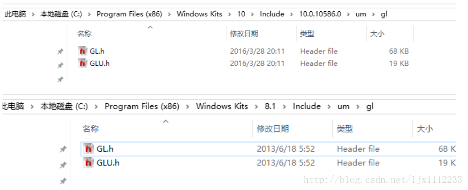
1, In C:\Program Files (x86)\ WindowKits \10\Include\10.0.10586.0\um\ GL or C:\Program Files (x86)\ WindowKits \8.1\Include\um\ GL there are GL.H and GLU.H;

 
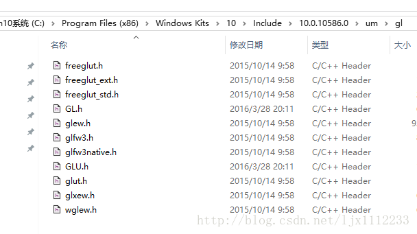
The freeglut. J h, freeglut_ext. J h, freeglut_std. J h, glew. J h, glfw3. J h, glfw3native. J h, glut. J h, glxew. J h, wglew. J h, GLU. H and gl. H in C: \ Program Files \ Windows (x86) Kits 10 \ \ Include \ 10.0.10586.0 \ um \ gl or C: \ Program Files (x86) Kits \ Windows \ \ Include \ 8.1 um \ gl.

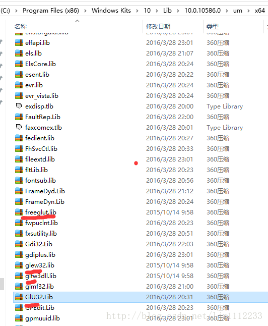
2, carry freeglut decompressed. Lib, glew32. Lib, glfw3dll. Lib, glu32. Lib, in the folder (C: \ Program Files \ Windows (x86) Kits 10 \ lib \ \ 10.0.10586.0 and, um, x86″
C:\Program Files (x86)\Windows Kits\10\Lib\10.0.10586.0\ UM \x64).
There were glu32.lib and opengl32.lib


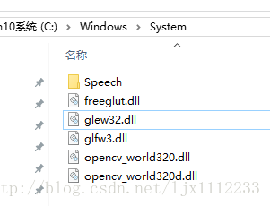
3, carry freeglut decompressed. DLL, glew32. DLL, glfw3. The DLL into the operating system directory under the system32 folder. (Location: C:\Windows\System32)
If it is a 64-bit operating System, copy it to C:\Windows\System

Two VC engineering configuration:
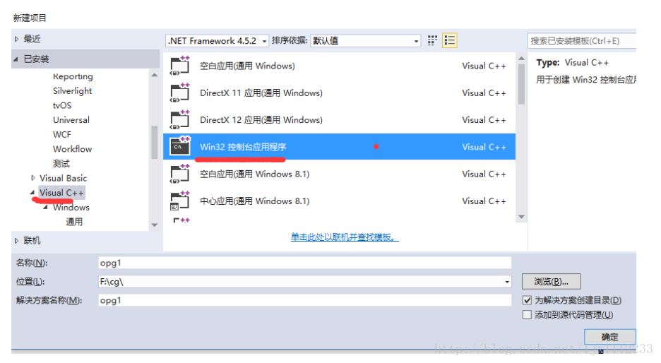
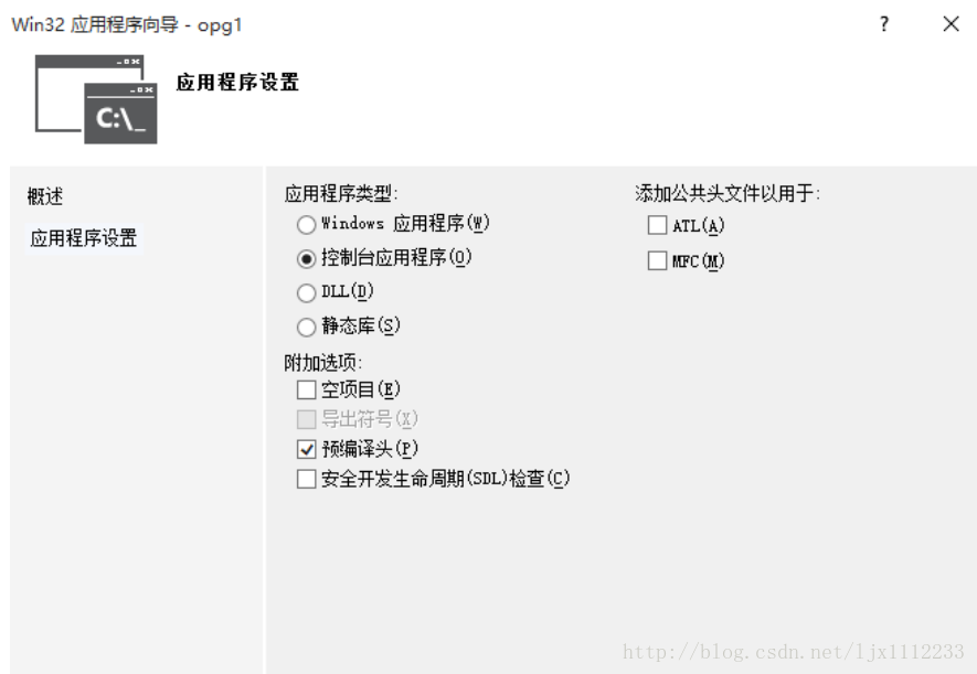
1) Create a Win32 Console Application.


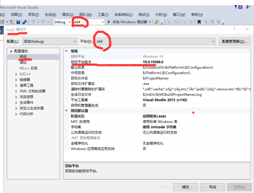
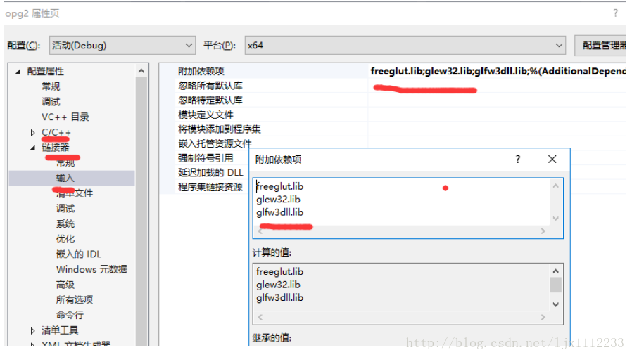
2) Link to OpenGL libraries. Right click on Project — property,
 
The Settings are as follows:


I’m going to put FreeGlut.Lib first; glew32.lib; glfw3dll.lib;

Add semicolons between libraries; Or the enter key
 
3) Modify the code as follows:
#include “stdafx.h”
// opg1.cpp : Defines the entry point for the console application.
//
 
#include “stdafx.h”
# include “stdafx. H”
 
# include & lt; GL/glew.h>
# include & lt; GL/glut.h>
# include & lt; math.h>
void display(void)
{
GlClear (GL_COLOR_BUFFER_BIT); /* Clear all pixels */
GlColor3f (1.0, 1.0, 1.0);
GlBegin (GL_POLYGON);// the draw white polygon
GlVertex3f (0.25, 0.25, 0.0);
GlVertex3f (0.75, 0.25, 0.0);
GlVertex3f (0.75, 0.75, 0.0);
GlVertex3f (0.25, 0.75, 0.0);
GlEnd ();
GlFlush (); /* Start processing buffered OpenGL routines */
}
 
void init (void)
{
GlclearColor (0.0, 0.0, 0.0, 0.0, 0.0); /* select clearing color */
GlMatrixMode (GL_PROJECTION);
GlLoadIdentity ();
GlOrtho (0.0, 1.0, 0.0, 1.0, -1.0, 1.0); /* Initialize viewing values */
}
 
int main(int argc, char** argv)
{
GlutInit (& amp; argc, argv);
GlutInitDisplayMode (GLUT_SINGLE | GLUT_RGB);
GlutInitWindowSize (250, 250); /*Declare initial window size.*/
GlutInitWindowPosition (100, 100); /*Declare initial window position.*/
GlutCreateWindow (” hello “); /*Open window with “hello”in its title bar.*/
The init (); /*Call initialization routines.*/
GlutDisplayFunc (display); /*Register callback function to display graphics.*/
GlutMainLoop (); /*Enter main loop and process events.*/
Return 0; /* ANSI C requires main to return int. */
}
 
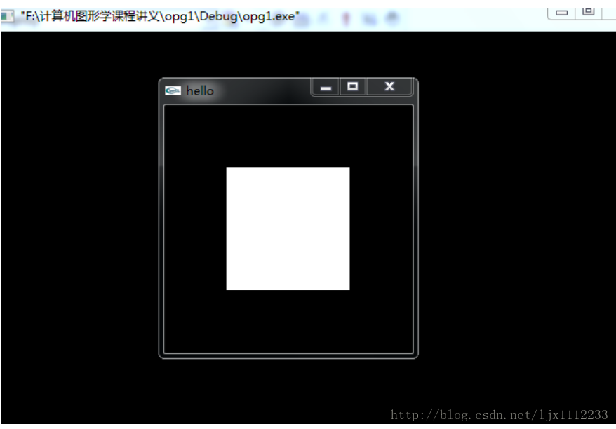
The compile run displays a white rectangle


Configure OpenGL development environment (glfw3 + glad) once and for all with visual studio

primers
There are many versions of OpenGL, we need to introduce additional third-party libraries to meet our usual rendering needs, which is more troublesome for students who just started learning.
I also met many many times behind the configuration of the tutorial, wasted time, also their technology and modern technology of OpenGL.
(2018), at the current time from learning OpenGL if glBegin () and a glEnd () that a is behind The Times, this tutorial is to demonstrate how to configure OpenGL3.3 over the environment.
> Learn the OpenGL tutorial: Learnopengl, you may need over the wall, there is a Chinese translation.
If you want to learn OpenGL quickly, here is the configured environment: (open it directly in VS2015 or above, Win7/10 test)
perlink: Resources
(> header files, lib files, DLLs used in the directory structure are also in this link)
The directory structure
The environment we configured is not only responsible for storing code and third party lib, but also some shader files and resource files, so we need to build a good directory structure.
The full configuration directory structure is as follows:

tr> <>> vsbuild> td>

/ table> <>d>
name

note

SRC

store code

external \ include

third-party library header files, Contains stb_image. J h, glad. J h, GLFW. J h, assimp. H such as

external \ lib

third-party libraries of lib

external \ DLL

third-party library DLL

resources

resource folder,
>
Focus on the folders under external\include
GLM OpenGL mathematical library, defined a lot of vector, matrix operations, concise and fast. GLFW is a cross-platform abstract library of window resources. Glad has different OpenGL implementations for different graphics card drivers, Glad helps us hide these differences and happily use OpenGL. STB_IMAGE lightweight library for reading images ASSIMP lightweight library for reading models
We have, so to speak, all the common components except the physics engine and sound control.
Now let’s construct the directory structure from scratch.
> First find an empty folder and create the following directory structure in it:

Instead of creating a vsbuild, VS will do it for us.
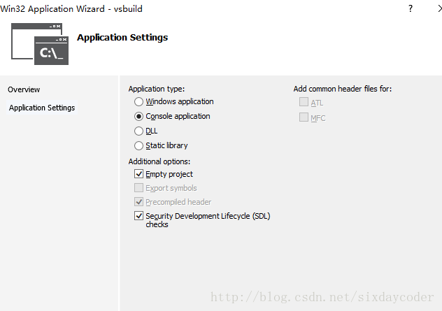
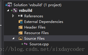
> Open Visual Studio and create an empty project. The project name is vsbuild.

After creation:

Next we need to configure lib, include to be introduced into our project.
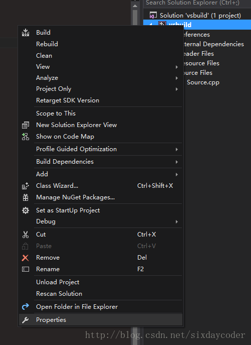
Right-click on the vsbuild project and open the properties page:

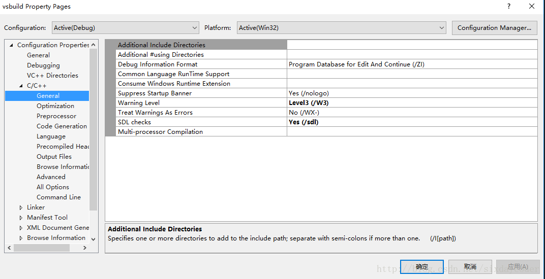
Find the C/C++ Genral

note that the C/C++ option only appears when you create a new.cpp file)
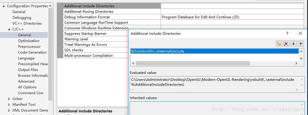
E>the additional directory on the right:

Note that SolutionDir is a macro that represents the directory where VSBuild is located, so we can find External/Include relative to it.
(Type the information $(SolutionDir)… , external, include).
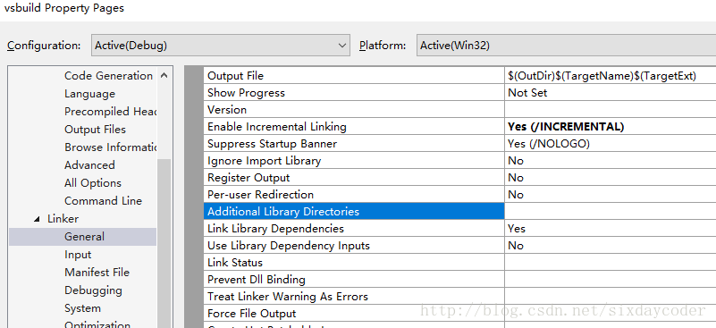
Similarly, select the additional library directory for Linker’s General

Open Edit:

In addition, open the Linker Input directory and enter the following values:


glfw3.lib
ad.lib
s>mage.lib
assimp.>
SolutionDir \external\lib
(here I compiled glad and stb_image into static libraries)
nally, because ASSIMP requires dynamic linking, we need to import the corresponding DLL into our project.
The easiest way to do this is as follows:

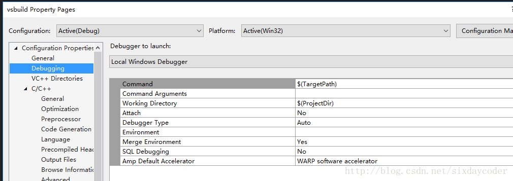
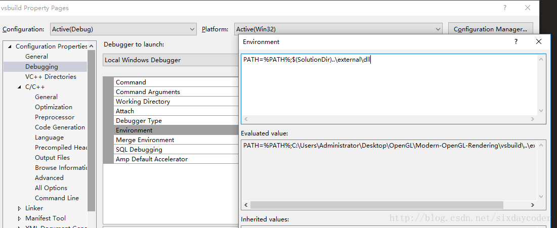
Select Debug and edit the environment entry:

The meaning of this line is to temporarily add the EXTERNAL \ DLL directory to the environment variable in debug mode so that we can successfully dynamically link.
After the configuration is complete, paste the following code into source.cpp and run.

#include <glad\glad.h>
#include <glfw\glfw3.h>
#include <iostream>


void framebuffer_size_callback(GLFWwindow* window, int width, int height);

void processInput(GLFWwindow *window);


// settings

const unsigned int SCR_WIDTH = 800;

const unsigned int SCR_HEIGHT = 600;


int main()

{

    // glfw: initialize and configure

    // ------------------------------

    glfwInit();

    glfwWindowHint(GLFW_CONTEXT_VERSION_MAJOR, 3);

    glfwWindowHint(GLFW_CONTEXT_VERSION_MINOR, 3);

    glfwWindowHint(GLFW_OPENGL_PROFILE, GLFW_OPENGL_CORE_PROFILE);


#ifdef __APPLE__

    glfwWindowHint(GLFW_OPENGL_FORWARD_COMPAT, GL_TRUE); // uncomment this statement to fix compilation on OS X

#endif


                                                         // glfw window creation

                                                         // --------------------

    GLFWwindow* window = glfwCreateWindow(SCR_WIDTH, SCR_HEIGHT, "LearnOpenGL", NULL, NULL);

    if (window == NULL)

    {

        std::cout << "Failed to create GLFW window" << std::endl;

        glfwTerminate();

        return -1;

    }

    glfwMakeContextCurrent(window);

    glfwSetFramebufferSizeCallback(window, framebuffer_size_callback);


    // glad: load all OpenGL function pointers

    // ---------------------------------------

    if (!gladLoadGLLoader((GLADloadproc)glfwGetProcAddress))

    {

        std::cout << "Failed to initialize GLAD" << std::endl;

        return -1;

    }


    // render loop

    // -----------

    while (!glfwWindowShouldClose(window))

    {

        // input

        // -----

        processInput(window);


        // render

        // ------

        glClearColor(0.2f, 0.3f, 0.3f, 1.0f);

        glClear(GL_COLOR_BUFFER_BIT);


        // glfw: swap buffers and poll IO events (keys pressed/released, mouse moved etc.)

        // -------------------------------------------------------------------------------

        glfwSwapBuffers(window);

        glfwPollEvents();

    }


    // glfw: terminate, clearing all previously allocated GLFW resources.

    // ------------------------------------------------------------------

    glfwTerminate();

    return 0;

}


// process all input: query GLFW whether relevant keys are pressed/released this frame and react accordingly

// ---------------------------------------------------------------------------------------------------------

void processInput(GLFWwindow *window)

{

    if (glfwGetKey(window, GLFW_KEY_ESCAPE) == GLFW_PRESS)

        glfwSetWindowShouldClose(window, true);

}


// glfw: whenever the window size changed (by OS or user resize) this callback function executes

// ---------------------------------------------------------------------------------------------

void framebuffer_size_callback(GLFWwindow* window, int width, int height)

{

    // make sure the viewport matches the new window dimensions; note that width and 

    // height will be significantly larger than specified on retina displays.

    glViewport(0, 0, width, height);

}

The following window shows that the configuration is successful.

Vs2019 OpenGL glut: error: unable to open include file: ‘GL / glut. H’: no such file or directory

The culprit
Updated vs2019
The solution
After the update, vs2019 installation directory (I) in disk C C: \ Program Files \ Microsoft Visual Studio (x86) \ 2019 \ Professional \ VC \ Tools \ MSVC will many a folder

to reconfigure the glut in the updated folder environment, as follows

    Put the file Glut. h in the path \Microsoft Visual Studio\2019\Professional\VC\Tools\MSVC\ New folder \ Include \ GL. Put Glut. lib and Glut32.lib under the \Microsoft Visual Studio\2019\Professional\VC\Tools\MSVC\ New folder \ Lib \x86 path.

Problems encountered in running OpenGL

Problems running OpenGL with VS
Problem 1. Linker tool error The link2026XXX module is not secure for the SAFESEH image
Solution:

1. Open the Property Pages dialog box for the project.
2. Click the Linker folder.
3. Click the Command Line property page.
4. Type /SAFESEH:NO into the Additional Options box and click Apply.

Reference: http://www.cnblogs.com/hanxi/archive/2012/06/10/2544230.html

Problem 2. The computer is missing GLUT32.DLL
Solution:
1. Check to see if it is in the Windows/System32 folder
2. If it is a 64-bit system, check to see if it is in the Windows/SYSWOW64 folder

Graphics rendering pipeline diagram of OpenGL

A, an overview of the
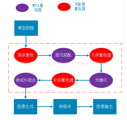
The current version of OpenGL is 3.3, which is based on the renderable pipeline to achieve model generation, rendering, image output and other work.
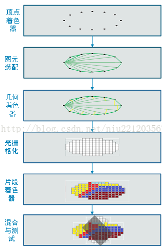
The Render Pipeline is a series of processing of three dimensional vertices into two dimensional discrete pixels. And the user can configure freely in specific shading phases (such as vertex shading and fragment shading phases, which is the biggest difference from fixed pipeline). The brief flow of the renderable pipeline is shown below.

Second, detailed process
The figure above is basically correct, but it’s not very intuitive. How does a three-dimensional vertex transform into a pixel?I’m going to break it down into two big steps, two dimensional vertices, two dimensional vertices discretization.
1. Transformation of three-dimensional coordinates into two-dimensional coordinates
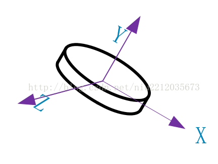
(1) Model vertex construction

Model vertices are built relative to the model’s own coordinates, namely object coordinates. Only the shape of the model can be expressed, and its position and attitude cannot be obtained, so world coordinates must be introduced.

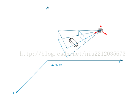
(2) Convert to world coordinates

The world coordinates represent a larger coordinate domain, and each vertex of the model can be represented by the world coordinates. From the object coordinates to the world coordinates, you have to multiply by a world matrix, and you get the model of the relative world coordinates.

(3) World coordinate transformation camera coordinates

The world coordinate transformation of camera coordinates, from object coordinates to world coordinates, is multiplied by an observation matrix, which gives the model relative to the camera coordinates.

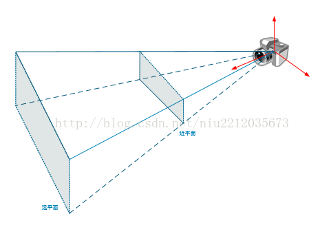
(4) Camera coordinate transformation screen coordinate 1

Camera coordinates transform screen coordinates. Any three – dimensional mode is displayed in two – dimensional form (screen). So a three-dimensional model is usually converted to a two-dimensional model. The first step is to build the cone with the camera as the origin.

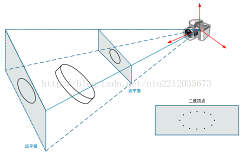
(5) Camera coordinate transformation screen coordinate 2

Next, the 3D coordinates of the model are transformed to 2D coordinates, which are multiplied by the perspective matrix. Finally, a 2D model is projected onto the near plane of the cone.

2, 2D vertex pixelation

The vertices obtained by perspective projection are linear and cannot be displayed on the screen. They need to be pixelated, as shown in the following figure:

Common problems and solutions under Linux

Common problems and solutions under Linux

. What are tar,.tar.gz,.bz2,.tar.bz2,.bz,.gz files and how do I unlock them?
They are both file (compressed) packages. Tar.gz: package and compress: tar CVF *.tar dirName: tar XVF *.tar
.tar.gz: package and compress: tar CZVF *.tar.gz
2: unpack: bzip2-d *.bz2
.b>unpack: bzip2-d *.bz
.bz: unpack: bzip2-d *.bz
.gz: unpac> Gzip-d *.gz


rh8 There is a graphical interface under the software File-roller to do this. Also can use unzip *. Zip unzip file, unrar *. Rar solution
open RAR file, but the general system does not come with unrar, to download the Internet.

br>

>
a. Create a directory like mkdir a
. Mount the iso file: mount -o loop XXXX.

Delete all files in the directory including subdirectories
-rf directory names

cat /proc/ cpuinfo-CPU (i.e. vendor, Mhz, flags like MMX)
t /proc/interrupts – interrupt
c> proc/ioports – device IO port
cat/p>/ meminfo-memory (i.e. mem used, free, i.e. mem used, free, Swap the size)
the cat/proc/partitions – all equipment all partitions
the cat/proc/pci – pci devices information
the cat/proc/swaps – all the swap partition information
the cat/proc/version – Linux version number Equivalent to the uname -r
uname -a – see system information such as the kernel

RPM -qpl aaa. RPM
RPM -qpl aaa
Gz
tar XVFZ example.tar.gz
tar XVFZ example.tgz
t>vf example.tar
unzip e>le.zip

> Gaim 0.58:

www.linuxsir.org/gaim/gaim-0.58-2.i386.rpm download QQ plug-in for gcc2.9 version

www.linuxsir.org/gaim/libqq-0.0.3-ft-0.58-gcc296.so.gz will download file into the/temp directory, then delete the existing Gaim system, namely, type the command in a terminal emulator: RPM -e Gaim.
Start the installation
en the terminal emulator and continue to install Gaim version 0.58, that is:
c>temp (go to the temp directory)
RPM -iv>im -0.58-2.i386. RPM (install software)
When the inst>tion is successful, you can create the Gaim icon on the GNome or KDE desktop.
To continue installing the QQ plugin, type the command:
nzip libq-0.0.3-ft-0.58 -gcc296.so.gz (unzip the file)
c>bq-0.0.3-ft-0.58 -gcc296.so /usr/lib/gaim (copy the plugin to the gaim library directory)
Softwar>ttings
Login screen> will appear when you first start Gaim version 0.85. Select “Plugins” first, and click “Load” in the “Plugins” dialog box. Load
libmsn.so and libq-0.0.3-FT-0.58-gcc296.so files respectively, and close them after confirmation. Then choose “all accounts”, in the presence of
account in the editor to click “add”, when the modify account page, we can enter your QQ or MSN number,
the login name fill in QQ number or MSN email, password to fill in the corresponding QQ or MSN password, Alias to fill in their nicknames, protocol selection
corresponding QQ or MSN, other Settings by default. When all Settings are completed, you can log in and use.
http://wangzhihng.blog.163.com/blog/static/350999420061030105134290/

Common problems of shadow map in OpenGL

Shadow maps are a common technique in games,
The principle is to view the entire scene from the light space with the light viewing matrix (binding the depth cache with the frame cache), and the resulting scene is not rendered
The second drawing, the depth buffer into the shader, all point transformation to the light space, the z coordinates, and the depth of the original cache value contrast, if the resulting value is less than the value of the depth buffer is proved that the pixels in the most close to the rear of the light source location, so this point can’t render, reason for shadow covered place.
This is what I get, the light source is rotated around (0,0,0) with a radius of 50. In the middle is a physical model. The entire lighting system is the simplest (an improved version of Feng’s lighting).

Problem 1. Boundary problem: there is a plane in front of the light source, the space outside the plane is the area affected by light, and the area inside the plane is the area not affected by light.

The problem is very simple. In the light space analysis, the light space, like the view space, has a cone:

The areas outside the cone that are not located on the upper ledge are all clipped out of the light space.
To make the cone black outside the edge, since the second time the shader calls the depth cache, it will also call some areas in the depth cache, which will result in the wrong result on the boundary.
To solve this problem, when setting the depth cache, you need to set all colors outside the bounds to black :


And that will give you the right answer.
Problem 2. Texture error
Textures are rendered in striped red, blue and green colors.
This is because the texture is not formatted correctly, the image is formatted in RGBA format, but the texture is formatted in RGB format, which will result in the wrong result:

As shown in the figure above, setting the image format to GL_RGBA will solve this problem when reading the image from the library

Problem 3. Follow the tutorial, but there are no shadows, the whole scene is bright
If there is no compiler error in the shader, please check whether the two matrix Settings are consistent (that is, whether the matrix of optical space is directly passed into the second shader).
In the second shading, set the observation matrix to the light space matrix to see if the whole scene can be seen in the light space observation matrix.
If the whole scene is not visible in light space, the entire depth cache is infinite (i.e. 1.0F), and all the points are in front of the occlusion, so you will see the whole scene lit up.
Question 4. According to the tutorial to write, there is no shadow, the whole scene is dark
The problem may be that your light source is so close to the model that the whole scene is completely blocked by the model from the light space. Another possibility is that the first rendering of the depth cache was not written,
This also results in the equivalent of a large flat surface in front of you.
Question 5. Where there is shadow, there is light, and where there is light, there is shadow
The reason for this problem is that there is a logic error in the shader of the second rendering, and the shadow is 1, which means there is a shadow (for example in Learnopengl tutorial). Therefore, it is necessary to use (1-shadow) in the final calculation of Feng’s illumination.
Multiplied by stolid and ambient, not shadow
Problem six. A layer of gray, according to the tutorial to eliminate but not the effect
The gray is caused by the principle defect of Shadowmap. It is possible that multiple adjacent pixels of the rendered graph correspond to the depth value in the same depth cache, resulting in the wrong corresponding of the depth value, so there will be streaks.
If the tutorial minus the value of a fixed doesn’t work, minus the value can be more a little bit small. This means that you draw volume is very big, I draw when I was led to this situation, this is because the tutorial is a very small unit to draw, so it’s bigger than the offset, but I draw the unit is very big, (100.0 f) so I need to reduce the value of the more, you can test several times, each time reduce an order of magnitude, by the way, I use a value of 0.00001, this is a very small value, the results after the application of the this value is true.

There are some other problems, such as the resolution is not enough to lead to the edge is not clear and so on, this kind of problem can find some anti-aliasing method to solve, is to take the average edge.
If you have a problem can leave a message at the bottom, you can also find me to source.
(to be continued….)

Summary of OpenGL simple solar system simulation

For some herself also don’t know why, I have a strange tenderness in c + +, always have the urge to want to use c + + programming task, but I really don’t like to always inside the black box of the console input and output, and the operation mechanism of MFC temporarily and I don’t know, one is a string file has been completed, looking at halo, OpenGL is accord with the need, and there is a glut can help implement simple forms in the console, speak quite enough as a simple to use, complex use later to say again.
I am completely a beginner, with reference to the “OpenGL Introduction Tutorial” this document and some references on the network can be scraped together to complete this simple solar system model. (here to thank the makers of this tutorial and the sharer, I feel to write quite good, there is a download on the Internet, I am from baidu library to get, they also passed a to the resources) why is the solar system model?Because I love it, and a lot of people have done it, and I don’t understand it, but there’s a code to learn. Needless to say, the first on a renderings:

The starting point of any project should be a requirement analysis. The requirement is very simple, which is to display a model that looks like the solar system on the screen, and just look like it. It takes time and effort to make an accurate model of the solar system, and no one pays for it. Then the design phase, as object-oriented programming, look for the object, the eight planets in the solar system as well as the sun itself, in order to look more beautiful point, track should also be mapped, so the object has two, all objects to achieve a draw method, is used to draw themselves, to design a myObj parent class can be easily performed as part of the paint job, I think now that each orbit to a certain object, then the track can be used as a private attribute of the object, it should be a dependency. The class diagram is as follows:

The basic information for the star ASTER includes the radius of the star, the revolution period revolution_solar, the revolution period self, the orbit orbit, and the revolution radius distance. Orbit has only one radius property. There are also some auxiliary properties that are defined in the implementation and are not listed in the class diagram.
With the class diagram, you can enter the coding stage, the first need to configure the development environment, I am using VS2010, development is using OpenGL, download address Baidu Google, I do not remember the original download address, passed a copy to the resources inside. Tutorial there said to be integrated development libraries to vs inside, but I don’t like it, don’t often use it is not necessary to change the development environment, as long as it is good to set a single project, the DLL file to the operation of the generated files,. H file saved to the project folder,..lib file loaded in the code should be able to use relative paths, but I don’t know where the base path is temporarily, so chose to set the attributes of the project, particular way is:
Right-click the project name in the Solution Explorer and select Properties ->; Linker-> General, add an absolute lib directory to Additional Librarydirectories. The lib file is loaded using #pragma comment (lib).
There are many examples in the tutorial, and each knowledge point is also very clear, do not repeat. Inside I met a little problem when system is realized in lesson 5 day month, if you use the tutorial to the parameters of the inside, in the window is what also can’t see, but if I ten times to reduce the parameters of the unified, can appear normal, though I searched some articles of coordinate transformation, but at present still don’t know why will appear this problem, if such as morally scaling should not appear different results?Doesn’t OpenGL accept parameters that are too large?
Said a little bit about the questions about the gluLookAt function, may be my personal problem, in understanding the function of the time a little effort, this function has nine parameters, divided into three groups, the first group is about the viewpoint of movement, a viewpoint is initially at point (0, 0), if not after the perspective projection transformation of coordinates, then draw the images will appear in the view’s location, similar to someone put something in your eyes, things just don’t see behind, can move through the first coordinate, then draw the solution to the object, But the advantage of Glulookat is that you don’t have to calculate the position of every object. You can view it from any Angle. It doesn’t matter if you just plot on the plane of the xyz axis, but what if you want to see the whole system at 45 degrees or 75 degrees?The position of each object is not easy to calculate. The way I understand this function works is that the developer first draws the whole system in the coordinate system, and then realizes the change of observation Angle through this function, and OpenGL automatically calculates the relative position of each object. This function must be placed before the other coordinate changes, and I feel that it is executed in the last order of the system drawing. The above is irresponsible conjecture, without any theoretical support, hereby declare…
Well, going a bit too far, the second set of parameters are the coordinates of the center of the viewpoint. The perspective projection itself is a four-prism, and the line between the viewpoint and the center is the same as a perpendicular from the vertex to the bottom.
The third parameter is the direction, that is, what do you think of the observer, the tutorial says from the point of (0, 0) to the point of attachment to determine positive direction, such as if set to (0, 0), is similar to normal viewing screen, (0, 1, 0) means the person is in upside down the screen, (0, 0, 1) said looked down at the keyboard, (0, 1) said from behind the display looked down at the keyboard…
There are still some problems with lighting and material Settings, we will talk about it later. The whole project has been uploaded to resources, please download it if necessary.
The first time you set up the project, you mistakenly selected Windows Application, which can be found in Properties ->; Linker-> system-> Subsystem changes to Console.
Modify the icon of the Console program to add resource->; Open Resource. H and set the ID of your icon to a minimum. To open Resource. H, open the.rc file (select View Code) and then open it in an include&lt file. resource.h> Select Open Document.

076_ OpenGL graphics program development practice

OpenGL Graphic Program Development Practice
Delphi tutorial series books (076) “OpenGL graphics program development practice” (state) finishing Email: [email protected]
Download Address:
Pdf

Xie Danrui Publishing House: Northwestern Polytechnical University Press ISBN: 7561219393 Available Date: 2006-9-6 Published Date: August 2005 Open Book: 16 Page Number: 293 Edition: 1-1
Content abstract
As a kind of graphics industry standard, OpenGL is widely used in practical work and occupies a very important position. This book USES the Delphi programming environment about OpenGL function principle, mainly introduced the development of computer graphics and development present situation, the related theory of OpenGL and OpenGL characteristics and working principle, the basic knowledge of OpenGL and advanced application techniques, the last instance system and how to using the OpenGL technology, integrated complex three-dimensional realistic graphics. This book is well-structured, informative, innovative and practical. It can be used as a reference for undergraduate students, graduate students, scientific researchers and graphic and image developers.
preface
Visualization of scientific computation, computer animation and virtual reality are three hot research directions in the field of computer graphics in recent years. Their technical core is the rendering of three-dimensional realistic graphics. At present, 3D realistic graphics technology has been successfully and widely used in military, aerospace, aviation, medicine, geological exploration, 3D games and industrial CAD design and other fields, so that people can directly operate the physical information in the 3D graphics world, and directly communicate with the computer. This technology has unified the power of man and machine in an intuitive and natural way, and this revolutionary change will undoubtedly greatly improve the quality and efficiency of people’s work. Therefore, it is of great theoretical and practical significance to actively promote the research of computer graphics. OpenGL is the abbreviation of Open Graphics Library, which is a set of high performance Graphics processing system developed by SGI company. It is the software interface of Graphics hardware, meaning the Open Graphics Library. With OpenGL, programmers can create interactive applications to achieve realistic three-dimensional graphics and images, which can be used in many fields that require a high degree of simulation of the real world. Due to its openness and high reusability, it has now become an industry standard. OpenGL is designed to be independent of hardware, independent from the window system, running a variety of operating systems can be used on a variety of computers, and can work in the network environment in the client/server mode, is a professional graphics processing, scientific computing and other high-end application areas of the standard graphics library. OpenGL as a graphics industry standard, almost all the visual application development tools support OpenGL integration, such as Delphi, VC++, VB, JAVA and so on. However, the current introduction of OpenGL principle of the reference resources are almost based on C or VC++, which is familiar with the Delphi programming environment for the majority of developers, is undoubtedly a pity. As we all know, Delphi with its simple and easy to use visual development environment, high efficiency compiler, powerful PASCAL language in the field of visual development tools occupies a very important position. Based on the above factors, this book uses the Delphi programming environment to tell the principle of OpenGL function. The book consists of 16 chapters. Chapter 1 briefly introduces the development of computer graphics and the development of graphics and images. Chapter 2 and Chapter 3 introduce the Delphi programming foundation and object-oriented theory; Chapter 4 introduces the basic situation of OpenGL graphics library, OpenGL characteristics and working principle; Chapter 5 introduces the foundation of entity modeling and describes the basic drawing commands of OpenGL, including the description of point entity, line entity and surface entity. Chapter 6 introduces the theory of view transformation in OpenGL, including model transformation, view transformation, projection transformation, view-area transformation and matrix stack operation. Chapters 7 and 8 cover colors and lighting in OpenGL; Chapters 9 to 13 introduce the advanced application techniques of OpenGL, including blending, anti-aliasing, fog, display lists, bitmaps, fonts, texture mapping, frame caching, and animation. Chapter 14 introduces the evaluation program and the principle of nonuniform rational B-splines. Chapter 15 explains how interactive OpenGL works, including selection mechanisms and feedback mechanisms. As a conclusion, Chapter 16 systematically describes how to comprehensively use OpenGL technology to draw complex 3D realistic graphics through several examples. This book is well-structured and informative. Much of the source code provided in the book is compiled under the Delphi 7.0 environment. This book can not only be used as a college undergraduate, graduate study of computer graphics course, but also for research institutes of researchers, computer graphics and image developers have a high reference value. Xue Huifeng, Wu Huixin and Xie Danrui participated in the compilation of the book. In addition, Xia Xiaoye, Gao Xiong, Xu Rongyue and Bai Linfei also participated in the compilation. Due to the limited level, there are omissions and mistakes in the book, please readers friends criticism and correction. Author April 2005
directory
The first chapter graphics and image development status
1.1 The booming development of computer graphics
1.2 OpenGL leads the trend of graphic image development
1.3 Selection of development tools
The second chapter is Delphi language foundation
2.1 Delphi Integrated Development Environment
2.2 Basic concepts of Delphi language
2.3 Data types
2.4 Variables and Constants
2.5 Operators and expressions
2.6 Statements
2.7 Process and Function
Chapter 3 Object-Oriented Programming
3.1 Classes and Objects
3.2 Class declarations
Members of the 3.3 class
3.4 Three features of OOP
3.5 Class Operators
3.6 Objects
3.7 Exception Handling
Chapter 4 is an overview of OpenGL
4.1 History of OpenGL
4.2 Basic features of OpenGL
4.3 Architecture of OpenGL
4.4 OpenGL workflow
4.5 OpenGL function library
4.6 Basic graphics functions of OpenGL
4.7 Future and prospect of OpenGL
The fifth chapter is the foundation of entity modeling
5.1 Preparation before drawing
5.2 OpenGL data types and function forms
5.3 Description of basic geometric primitives
5.4 Using glBegin() and glEnd()
5.5 Normal vector
5.6 Draw basic primitive instances
Chapter 6 View transformation
6.1 Mathematical basis of graph transformation
6.2 From 3D Space to 2D Plane
6.3 View transformation and model transformation
6.4 Projection transformation
6.5 Visual area transformation
6.6 Additional cut plane
6.7 View transform instance
Chapter 7 Colors in OpenGL
7.1 Color perception
7.2 Colors in the computer
7.3 RGBA mode and color index mode
7.4 Specify the shadow model
7.5 Examples of color usage
Chapter 8 Light
8.1 Real World and OpenGL Lighting
8.2 Illumination Sphere Case Analysis
8.3 Create Light Source..
8.4 Select the lighting model
8.5 Define material properties
8.6 Illumination math calculation
8.7 Lighting in color index mode
Chapter 9 Mixing, anti-aliasing, fog
9.1 Mixing
9.2 Anti-aliasing
9.3 the fog
Chapter 10 shows the list
10.1 The basic concept of displaying lists
10.2 Show the creation and execution of lists
10.3 Show nested use of lists
10.4 Management of display lists
10.5 Multiple operations to display lists
10.6 Use display lists to change encapsulation mode
Chapter 11 Bitmaps, Characters, and Images
11.1 Bitmap
11.2 Characters
11.3 Images
Chapter 12 Texture Mapping
12.1 Basic steps for texture mapping
12.2 Specify the texture
12.3 Texture Control
12.4 Texture coordinates
Chapter 13 Frame Caching and Animation
13.1 frame cache
13.2 pixel segment testing and operation
13.3 Accumulate the cache
13.4 Dual cache animation
Chapter 14 Evaluation Procedures and Nonuniform Rational B-Splines
14.1 Evaluation procedure
14.2 NURBS curves and surfaces
Chapter 15 Selection and Feedback
15.1 Selection
15.2 Feedback
Chapter 16 OpenCL advanced application skills
16.1 Flames dancing
16.2 Three-dimensional trees
16.3 Texture Synthesis Application
References…