https://answer.uwa4d.com/question/5963507cf0ca5af37bff502c
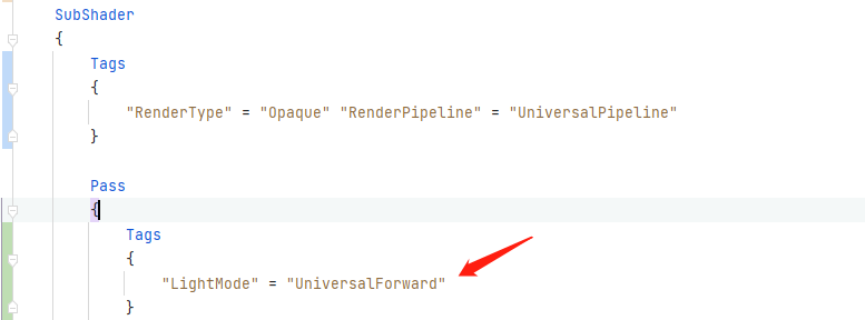
Maybe there is no lightmodel, as shown in the figure
- also reset the variant collector and put the shaders to be packaged in to ensure that the shaders are loaded
https://answer.uwa4d.com/question/5963507cf0ca5af37bff502c
Maybe there is no lightmodel, as shown in the figure
Model vertices are built relative to the model’s own coordinates, namely object coordinates. Only the shape of the model can be expressed, and its position and attitude cannot be obtained, so world coordinates must be introduced.
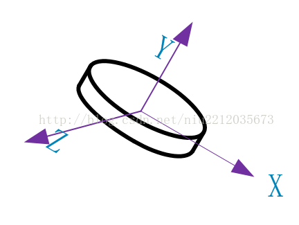
(2) Convert to world coordinates
The world coordinates represent a larger coordinate domain, and each vertex of the model can be represented by the world coordinates. From the object coordinates to the world coordinates, you have to multiply by a world matrix, and you get the model of the relative world coordinates.

(3) World coordinate transformation camera coordinates
The world coordinate transformation of camera coordinates, from object coordinates to world coordinates, is multiplied by an observation matrix, which gives the model relative to the camera coordinates.
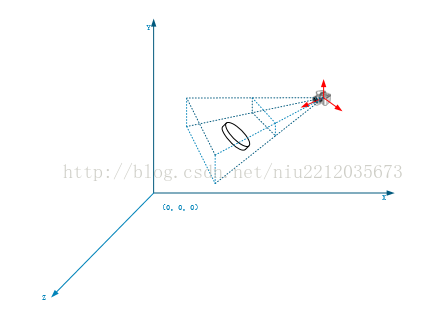
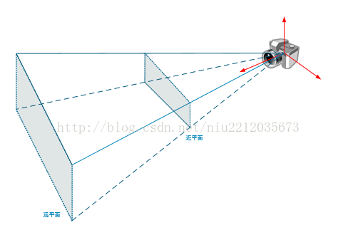
(4) Camera coordinate transformation screen coordinate 1
Camera coordinates transform screen coordinates. Any three – dimensional mode is displayed in two – dimensional form (screen). So a three-dimensional model is usually converted to a two-dimensional model. The first step is to build the cone with the camera as the origin.
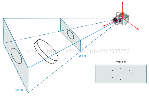
(5) Camera coordinate transformation screen coordinate 2
Next, the 3D coordinates of the model are transformed to 2D coordinates, which are multiplied by the perspective matrix. Finally, a 2D model is projected onto the near plane of the cone.
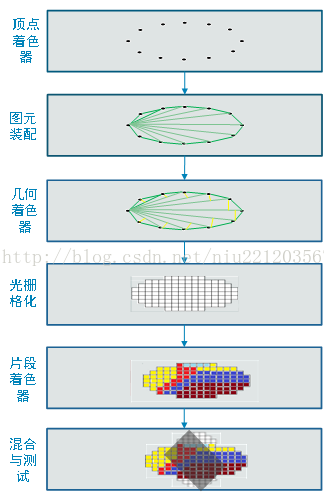
2, 2D vertex pixelation
The vertices obtained by perspective projection are linear and cannot be displayed on the screen. They need to be pixelated, as shown in the following figure:
OpenGL pit record
The 3D model is loaded with OpenGL RBO texture cache
3D model loading
When working with 3D models, we often create an FBO first, and the FBO is associated with Texture and RBO. The first time we rendered it, we rendered it directly to the FBO associated texture, then went through the other texture filters and displayed it again.
There are a couple of caveats here.
Rendering must be associated with an RBO. Turn Depth Test on before rendering off-screen and always turn it off after rendering off-screen. Do another render operation, otherwise render black screen texture will appear.
OpenGL RBO
Sometimes when OpenGL uses the depth buffer, the rendering effect disappears completely, and that’s probably because the depth buffer has been turned off.
The name of the
GLDepthMask – Enables or disables write depth buffers
C specification
void glDepthMask( GLboolean flag);
parameter
flag
Specifies whether the enabled depth buffer can be written. If flag is GL_FALSE, the depth buffer write is disabled. Otherwise, it can be enabled. The initial state is to enable deep buffer writes.
describe
GLDepthMask specifies whether the enabled depth buffer can be written. If flag is GL_FALSE, the depth buffer write is disabled. Otherwise, it can be enabled. The initial state is to enable deep buffer writes.
Related Gets
GL_DEPTH_WRITEMASK glGet parameters
See also
GLColorMask, GLDepthFunc, GLDepThrangef, GLStencilMask
copyright
https://www.khronos.org/registry/OpenGL-Refpages/es2.0/xhtml/glDepthMask.xml
https://blog.csdn.net/flycatdeng
Texture cache
To create a texture cache, you must specify the size of memory for the texture.
public static int createTextureObject(int textureTarget, int width, int height) {
        int[] textures = new int[1];
        GLES20.glGenTextures(1, textures, 0);
        GlUtil.checkGlError("glGenTextures");

        int texId = textures[0];
        GLES20.glBindTexture(textureTarget, texId);
        GlUtil.checkGlError("glBindTexture " + texId);

        GLES20.glTexParameterf(textureTarget, GLES20.GL_TEXTURE_MIN_FILTER, GLES20.GL_LINEAR);
        GLES20.glTexParameterf(textureTarget, GLES20.GL_TEXTURE_MAG_FILTER, GLES20.GL_LINEAR);
        GLES20.glTexParameteri(textureTarget, GLES20.GL_TEXTURE_WRAP_S, GLES20.GL_CLAMP_TO_EDGE);
        GLES20.glTexParameteri(textureTarget, GLES20.GL_TEXTURE_WRAP_T, GLES20.GL_CLAMP_TO_EDGE);
        GlUtil.checkGlError("glTexParameter");
        GLES20.glTexImage2D(GLES20.GL_TEXTURE_2D, 0, GLES20.GL_RGBA, width, height, 0, GLES20.GL_RGBA, GLES20.GL_UNSIGNED_BYTE, null);
        return texId;
    }