The current version of OpenGL is 3.3, which is based on the renderable pipeline to achieve model generation, rendering, image output and other work.
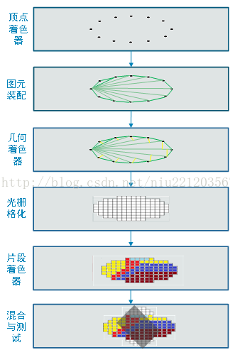
The Render Pipeline is a series of processing of three dimensional vertices into two dimensional discrete pixels. And the user can configure freely in specific shading phases (such as vertex shading and fragment shading phases, which is the biggest difference from fixed pipeline). The brief flow of the renderable pipeline is shown below.
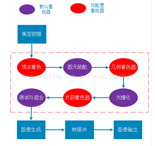
Second, detailed process
The figure above is basically correct, but it’s not very intuitive. How does a three-dimensional vertex transform into a pixel?I’m going to break it down into two big steps, two dimensional vertices, two dimensional vertices discretization.
1. Transformation of three-dimensional coordinates into two-dimensional coordinates
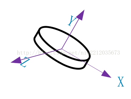
(1) Model vertex construction
Model vertices are built relative to the model’s own coordinates, namely object coordinates. Only the shape of the model can be expressed, and its position and attitude cannot be obtained, so world coordinates must be introduced.
(2) Convert to world coordinates
The world coordinates represent a larger coordinate domain, and each vertex of the model can be represented by the world coordinates. From the object coordinates to the world coordinates, you have to multiply by a world matrix, and you get the model of the relative world coordinates.

(3) World coordinate transformation camera coordinates
The world coordinate transformation of camera coordinates, from object coordinates to world coordinates, is multiplied by an observation matrix, which gives the model relative to the camera coordinates.
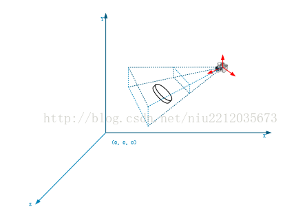
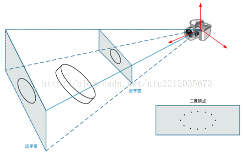
(4) Camera coordinate transformation screen coordinate 1
Camera coordinates transform screen coordinates. Any three – dimensional mode is displayed in two – dimensional form (screen). So a three-dimensional model is usually converted to a two-dimensional model. The first step is to build the cone with the camera as the origin.
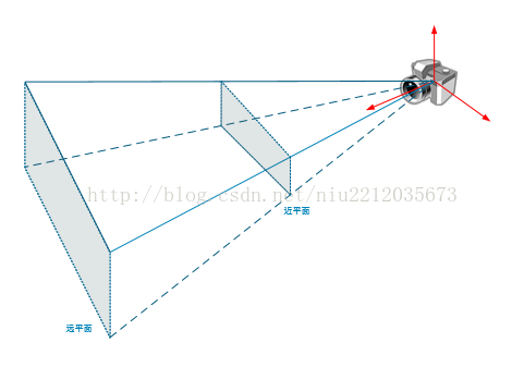
(5) Camera coordinate transformation screen coordinate 2
Next, the 3D coordinates of the model are transformed to 2D coordinates, which are multiplied by the perspective matrix. Finally, a 2D model is projected onto the near plane of the cone.
2, 2D vertex pixelation
The vertices obtained by perspective projection are linear and cannot be displayed on the screen. They need to be pixelated, as shown in the following figure:
Read More:
- OpenGL basic graphics programming – OpenGL and 3D graphics world
- 076_ OpenGL graphics program development practice
- 2016.11.1 OpenGL learning, black screen does not display graphics
- [181124] VC + + use OpenGL to draw 3D graphics example source code
- Rendering Problems :Failed to load platform rendering library
- Rendering Problems Exception raised during rendering:
- VC + + OpenGL is used as the development platform to design the program, which can generate any pixel on the screen, and use the pixel to draw the basic graphics
- Many unknown pins appear when converting the schematic diagram of Altium design to PCB
- R ggplot Error in .Call.graphics(C_palette2, .Call(C_palette2, NULL)): invalid graphics state
- Error in .Call.graphics(C_palette2, .Call(C_palette2, NULL)) : invalid graphics state
- Solution to the problem of multiple parameters when using pipeline under Linux
- R language – error analysis – error in Call.graphics (C_ palette2, .Call(C_ palette2, NULL)) : invalid graphics state
- Use subprocess to execute the command line, and the pipeline is blocked
- Introduction to the principle of Mali tile based rendering
- How to solve the problem of “unable to open / dev / vmmon: broken pipeline” when running VMware virtual machine?
- Failed to load platform rendering library
- Content rendering error: a solution to the problem of zero Download document cannot be opened
- OpenGL learning — problems encountered in compiling OpenGL program for the first time
- Error in compiling pcl1.9.1: “class vtkdatasetmapper” has no member named “immediatemode rendering off”
- [solution] the system is running in low graphics mode