1, using VTK in Qt vtkOrientationMarkerWidget don’t show the coordinates of the control problem

Change the above code to the following
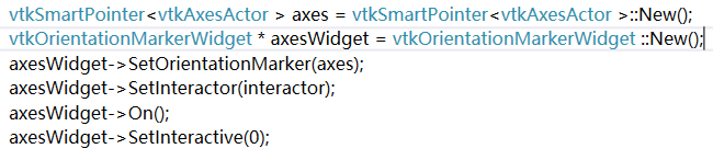
Change the above code to the following
<span style="font-size:14px;">  // Description:
  // Delete a VTK object.  This method should always be used to delete
  // an object when the New() method was used to create it. Using the
  // C++ delete method will not work with reference counting.
  virtual void Delete();

  // Description:
  // Delete a reference to this object.  This version will not invoke
  // garbage collection and can potentially leak the object if it is
  // part of a reference loop.  Use this method only when it is known
  // that the object has another reference and would not be collected
  // if a full garbage collection check were done.
  virtual void FastDelete();</span>
Possible reasons:
The Activiz.net library downloaded on the CPU version does not match the local CPU version
>
download Activiz.net source code compilation of anyCPU version of the library.
Activiz.net source: https://github.com/bitzhuwei/Kitware.VTK.git
>
>
>
>
>
>
>
>
>
>
>
>
2, select Kitware project right click modify project properties – “build -” target platform anyCPU compilation
=
=
=
=
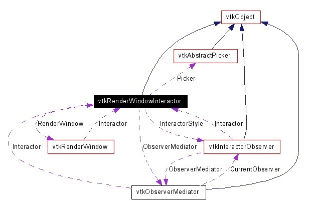
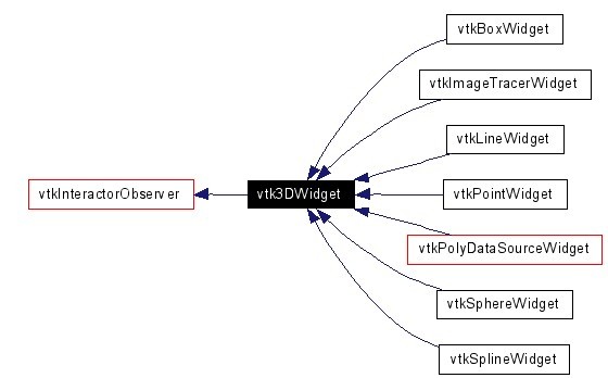
When embedding VTK qt met VTK widget can’t move, began to directly copy the official case inside vtkScalarBarWidget wording, is shown in the QVTKRenderWindowInteractor abnormalities, cannot interact with the widget.
https://vtk.org/Wiki/VTK/Examples/Python/Widgets/ScalarBarWidget
in writing is as follows:
# create the scalar_bar_widget
scalar_bar_widget = vtk.vtkScalarBarWidget()
scalar_bar_widget.SetInteractor(interactor)
scalar_bar_widget.SetScalarBarActor(scalar_bar)
scalar_bar_widget.On()
Changed to:
# create the scalar_bar_widget
self.scalar_bar_widget = vtk.vtkScalarBarWidget()
self.scalar_bar_widget.SetInteractor(self.iren)
self.scalar_bar_widget.SetScalarBarActor(scalar_bar)
self.scalar_bar_widget.On()
This means that the widget should be prefixed with self when loading with classes.
>
from PyQt5 import QtWidgets
from PyQt5.QtWidgets import QApplication
from vtk.qt.QVTKRenderWindowInteractor import QVTKRenderWindowInteractor
import sys
import vtk
class MainPage(QtWidgets.QMainWindow):
    def __init__(self, parent=None):
        QtWidgets.QMainWindow.__init__(self, parent)
        self.setObjectName("MainWindow")
        self.resize(603, 553)
        self.centralWidget = QtWidgets.QWidget(self)
        self.gridlayout = QtWidgets.QGridLayout(self.centralWidget)
        self.vtkWidget = QVTKRenderWindowInteractor(self.centralWidget)
        self.gridlayout.addWidget(self.vtkWidget)
        self.setCentralWidget(self.centralWidget)
        self.ren = vtk.vtkRenderer()
        self.vtkWidget.GetRenderWindow().AddRenderer(self.ren)
        self.iren = self.vtkWidget.GetRenderWindow().GetInteractor()
        # Create source
        source = vtk.vtkSphereSource()
        source.SetCenter(0, 0, 0)
        source.SetRadius(5.0)
        # Create a mapper
        mapper = vtk.vtkPolyDataMapper()
        mapper.SetInputConnection(source.GetOutputPort())
        # Create an actor
        actor = vtk.vtkActor()
        actor.SetMapper(mapper)
        self.ren.AddActor(actor)
        # create the scalar_bar
        scalar_bar = vtk.vtkScalarBarActor()
        scalar_bar.SetOrientationToHorizontal()
        lut = vtk.vtkLookupTable()
        lut.Build()
        scalar_bar.SetLookupTable(lut)
        # create the scalar_bar_widget
        self.scalar_bar_widget = vtk.vtkScalarBarWidget()
        self.scalar_bar_widget.SetInteractor(self.iren)
        self.scalar_bar_widget.SetScalarBarActor(scalar_bar)
        self.scalar_bar_widget.On()
if __name__ == "__main__":
    app = QApplication(sys.argv)
    window = MainPage()
    window.show()
    window.iren.Initialize()
    sys.exit(app.exec_())
Qt program in the Haysi HI3531A development board, update() repeatedly after the refresh interface program abnormal crash
Hi3531a qt program after the operation, many times after the update program hang up at http://www.ebaina.com/bbs/forum.php?mod=viewthread& tid=23327& fromuid=19660
(Source: Ebna Forum)
The problem
Open the packed program found collapse.
program is made up of two interface. After the first interface is login screen, click login will invoke the other main interface
login interface can open, there is no problem, call the main interface will collapse.
screening
I read it first
https://blog.csdn.net/cqltbe131421/article/details/78036684 the bosses of explanation.
Maybe it’s the pointer. Or event.
comments one by one code hou found the root cause again
inside the constructor USES a

program package after infinite collapse.
no problem after the 63 lines of code commented out.
thinking
Because my ExcelViewModel is an empty object. Inside the constructor does not have any code.
I wonder whether the problem.
later 
Added a line of setHeaderData () , the main is to set up the command excelViewModel data in it, and set the column number.
then collapse.
#include <vtkCylinderSource.h>
#include <vtkLineSource.h>
#include <vtkPolyData.h>
#include <vtkSmartPointer.h>
#include <vtkPolyDataMapper.h>
#include <vtkActor.h>
#include <vtkRenderWindow.h>
#include <vtkRenderer.h>
#include <vtkRenderWindowInteractor.h>
#include <vtkProperty.h>
#include <vtkTubeFilter.h>
#include <vtkBMPReader.h>
#include <vtkJPEGReader.h>
#include <vtkTexture.h>
#include <vtkTextureMapToCylinder.h>
#include <vtkTransformTextureCoords.h>

int main(int argc, char* argv[])
{
	if (argc < 2)
	{
		std::cout << "Usage: " << argv[0] << " texture(.jpg)" << std::endl;
		return EXIT_FAILURE;
	}

	// Create a Cylinder
	vtkSmartPointer<vtkCylinderSource> cylinderSource =
		vtkSmartPointer<vtkCylinderSource>::New();
	cylinderSource->SetHeight(10.0);
	cylinderSource->SetCenter(0.0, 0.0, 0.0);
	cylinderSource->SetRadius(2.0);
	cylinderSource->SetResolution(50);

	// Load a jpeg file
	vtkSmartPointer<vtkJPEGReader> jpegReader =
		vtkSmartPointer<vtkJPEGReader>::New();
	jpegReader->SetFileName(argv[1]);

	vtkSmartPointer<vtkTexture> texture =
		vtkSmartPointer<vtkTexture>::New();
	texture->SetInputConnection(jpegReader->GetOutputPort());
	texture->InterpolateOn();

	// map two-dimensional to three-dimensional, use cylinder
	vtkSmartPointer<vtkTextureMapToCylinder> textureMap =
		vtkSmartPointer<vtkTextureMapToCylinder>::New();
	textureMap->SetInputConnection(cylinderSource->GetOutputPort());

	vtkSmartPointer<vtkTransformTextureCoords> transformTextureCoords =
		vtkSmartPointer<vtkTransformTextureCoords>::New();
	transformTextureCoords->SetInputConnection(textureMap->GetOutputPort());
	//transformTextureCoords->SetScale(1, 1, 0);

	vtkSmartPointer<vtkPolyDataMapper> cylinderMapper =
		vtkSmartPointer<vtkPolyDataMapper>::New();
	cylinderMapper->SetInputConnection(/*textureMap*/transformTextureCoords->GetOutputPort());

	vtkSmartPointer<vtkActor> cylinderActor =
		vtkSmartPointer<vtkActor>::New();
	cylinderActor->SetMapper(cylinderMapper);
	cylinderActor->SetTexture(texture);

	vtkSmartPointer<vtkRenderer> renderer =
		vtkSmartPointer<vtkRenderer>::New();
	vtkSmartPointer<vtkRenderWindow> renderWindow =
		vtkSmartPointer<vtkRenderWindow>::New();
	renderWindow->SetSize(600, 600);
	renderWindow->AddRenderer(renderer);
	vtkSmartPointer<vtkRenderWindowInteractor> renderWindowInteractor =
		vtkSmartPointer<vtkRenderWindowInteractor>::New();
	renderWindowInteractor->SetRenderWindow(renderWindow);

	renderer->AddActor(cylinderActor);

	renderWindow->Render();
	renderWindowInteractor->Start();

	return EXIT_SUCCESS;
}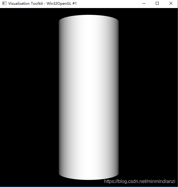
How to create a cylinder
The key code
vtkSmartPointer<vtkTexture> texture =
	vtkSmartPointer<vtkTexture>::New();
texture->SetInputConnection(/*bmpReader*/jpegReader->GetOutputPort());
texture->InterpolateOn();

// map two-dimensional to three-dimensional, use cylinder
vtkSmartPointer<vtkTextureMapToCylinder> textureMap =
	vtkSmartPointer<vtkTextureMapToCylinder>::New();
textureMap->SetInputConnection(cylinderSource->GetOutputPort());

vtkSmartPointer<vtkTransformTextureCoords> transformTextureCoords =
	vtkSmartPointer<vtkTransformTextureCoords>::New();
transformTextureCoords->SetInputConnection(textureMap->GetOutputPort());
//transformTextureCoords->SetScale(1, 1, 0);

vtkSmartPointer<vtkPolyDataMapper> cylinderMapper =
	vtkSmartPointer<vtkPolyDataMapper>::New();
cylinderMapper->SetInputConnection(/*textureMap*/transformTextureCoords->GetOutputPort());

vtkSmartPointer<vtkActor> cylinderActor =
	vtkSmartPointer<vtkActor>::New();
cylinderActor->SetMapper(cylinderMapper);
cylinderActor->SetTexture(texture);
rendering
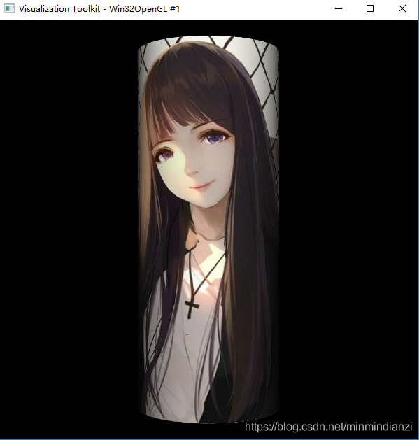
The complete code
Reference
VTK texture mapping principle introduction
VTK TransformTextRoots for texture mapping
VTK/Examples/Cxx/Texture/TexturedSphere

A slice is an image corresponding to a section of a three-dimensional image. The section can be a plane that passes through an inner point of the image and is parallel to the XY, YZ and XZ planes, or it can be any plane that passes through an inner point of the three-dimensional image in any direction. It is an important function of medical image browsing software to browse and analyze the internal tissue structure of images easily by extracting slices. In VTK, VTKImageReslice class realizes the function of image slice extraction.
Here is the code for slice extraction:#include <vtkAutoInit.h> VTK_MODULE_INIT(vtkRenderingOpenGL); #include <vtkSmartPointer.h> #include <vtkImageData.h> #include <vtkMetaImageReader.h> #include <vtkMatrix4x4.h> // #include <vtkImageReslice.h> #include <vtkLookupTable.h> #include <vtkImageMapToColors.h> #include <vtkImageActor.h> #include <vtkRenderer.h> #include <vtkRenderWindow.h> #include <vtkRenderWindowInteractor.h> #include <vtkInteractorStyleImage.h> int main(int argc, char* argv[]) { vtkSmartPointer<vtkMetaImageReader> reader = vtkSmartPointer<vtkMetaImageReader>::New(); reader->SetFileName("brain.mhd"); reader->Update(); int extent[6]; double spacing[3]; double origin[3]; reader->GetOutput()->GetExtent(extent); reader->GetOutput()->GetSpacing(spacing); reader->GetOutput()->GetOrigin(origin); double center[3]; center[0] = origin[0] + spacing[0] * 0.5 * (extent[0] + extent[1]); center[1] = origin[1] + spacing[1] * 0.5 * (extent[2] + extent[3]); center[2] = origin[2] + spacing[2] * 0.5 * (extent[4] + extent[5]); //*****************************************************************// static double axialElements[16] = { 1, 0, 0, 0, 0, 1, 0, 0, 0, 0, 1, 0, 0, 0, 0, 1 }; vtkSmartPointer<vtkMatrix4x4> resliceAxes = vtkSmartPointer<vtkMatrix4x4>::New(); resliceAxes->DeepCopy(axialElements); resliceAxes->SetElement(0, 3, center[0]); resliceAxes->SetElement(1, 3, center[1]); resliceAxes->SetElement(2, 3, center[2]); vtkSmartPointer<vtkImageReslice> reslice = vtkSmartPointer<vtkImageReslice>::New(); reslice->SetInputConnection(reader->GetOutputPort()); reslice->SetOutputDimensionality(2); reslice->SetResliceAxes(resliceAxes); reslice->SetInterpolationModeToLinear(); //*****************************************************************// vtkSmartPointer<vtkLookupTable> colorTable = vtkSmartPointer<vtkLookupTable>::New(); colorTable->SetRange(0, 1000); colorTable->SetValueRange(0.0, 1.0); colorTable->SetSaturationRange(0.0, 0.0); colorTable->SetRampToLinear(); colorTable->Build(); vtkSmartPointer<vtkImageMapToColors> colorMap = vtkSmartPointer<vtkImageMapToColors>::New(); colorMap->SetLookupTable(colorTable); colorMap->SetInputConnection(reslice->GetOutputPort()); //*****************************************************************// vtkSmartPointer<vtkImageActor> imgActor = vtkSmartPointer<vtkImageActor>::New(); imgActor->SetInputData(colorMap->GetOutput()); vtkSmartPointer<vtkRenderer> renderer = vtkSmartPointer<vtkRenderer>::New(); renderer->AddActor(imgActor); renderer->SetBackground(1.0, 1.0, 1.0); vtkSmartPointer<vtkRenderWindow> renderWindow = vtkSmartPointer<vtkRenderWindow>::New(); renderWindow->AddRenderer(renderer); renderWindow->Render(); renderWindow->SetSize(640, 480); renderWindow->SetWindowName("Extract3Dslice"); vtkSmartPointer<vtkRenderWindowInteractor> rwi = vtkSmartPointer<vtkRenderWindowInteractor>::New(); vtkSmartPointer<vtkInteractorStyleImage> imagestyle = vtkSmartPointer<vtkInteractorStyleImage>::New(); rwi->SetInteractorStyle(imagestyle); rwi->SetRenderWindow(renderWindow); rwi->Initialize(); rwi->Start(); return 0; }Firstly, a medical 3D image is read through VTK Metaimagereader, and the extent, origin and pixel interval of the image are obtained. From these three parameters, the center position of the image can be calculated. Next, we define the transformation matrix AxialElements. The first three columns of the matrix represent the x, y, and z vectors, and the fourth column represents the center coordinates.
AxialElements in the code represents a plane whose plane transformation matrix is consistent with the current coordinate system, whose plane is parallel to the XY plane, and whose plane is past the center point. Now, when you define that slice, it could be any plane, any plane, but you have to go through the interior of the image.
A common transformation matrix is given below.
Extraction of slices parallel to the XZ plane:static double coronalElements[16] = { 1, 0, 0, 0, 0, 0, 1, 0, 0,-1, 0, 0, 0, 0, 0, 1 };Extract slices parallel to the YZ plane:
static double sagittalElements[16] = {
0, 0,-1, 0,
1, 0, 0, 0,
0,-1, 0, 0,
0, 0, 0, 1 };
Extract oblique slice:
static double obliqueElements[16] = {
1, 0, 0, 0,
0, 0.866025, -0.5, 0,
0, 0.5, 0.866025, 0,
0, 0, 0, 1 };
Note that when using these transformation matrices, you need to replace the fourth column with a point coordinate of the image that the slice passes through. In the example above, add the center of the image to the AXIALElements matrix and set the transformation matrix with the function SetResliceAxes. SetOutputDimensionality(2) specifies that the output image is a two-dimensional image.
And function SetInterpolationModeToLinear () specifies the difference of edge extraction method for the linear difference, the class also provides other interpolation methods:
SetInterpolationModeToNearestNeighbor () : nearest neighbor approach
SetInterpolationModeToCubic () : three linear difference
After the setup is complete, execute Update() to complete the section calculation.The expected results provided by Dongling should be:
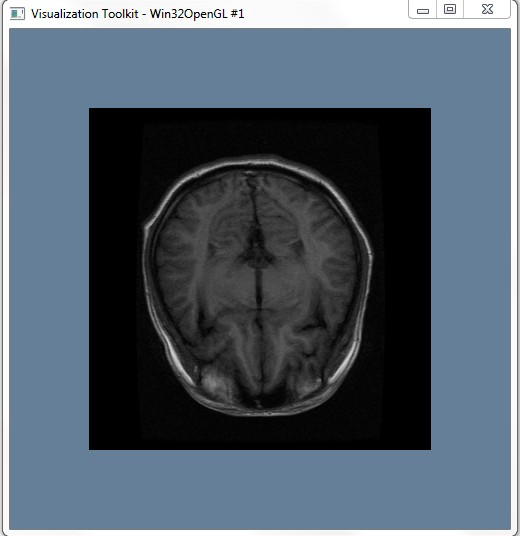
However, in the actual operation, we encountered the problem that VTKMetaimagereader could not read the file, which was normal in the previous 32bit system, and we are not sure where the problem appears temporarily, which needs further study!! Here are the questions:

2. See the data
1. C++ Primer
2. The VTK User’s Guide — 11 The Edition
3. The Visualization Toolkit — AnObject-Oriented Approach To 3D Graphics (4th Edition)
4. Zhang Xiaodong, Luo Huoling. Advance of VTK Graphics Image Development [M]. Machinery Industry Press, 2015.
The resources
[1] Use VTK to read a single TIFF image
[2]VTK Learning Notes -2-TIFF Image Data Resictioning
VTK profile
Outline the characteristics of the frame structure
An overview of the Frame structure The visualization model adopts the data flow model 5In this model, each module is connected in the network, and a series of operations on the data are realized by using the module. The characteristic of this model is that it is applicable to different data types and different algorithms, so it is very flexible. VTK uses a data stream approach to convert raw information into graphical data. There are two basic objects in this method: a Data Object and a Process Object.
Copyright Notice: All posts on this blog are licensed under the CC BY-NC-SA 4.0 license, unless otherwise stated. Reprint please indicate the source!
The VTK1Visualization Toolkit) is a free, open-source software Toolkit designed and developed by Kitware based on object-oriented programming techniques for image processing, 3D graphics, and visual programming. VTK is designed as a Toolkit rather than a system. It is an independent target library, which can be easily embedded into any development tool and developed its own library functions on the basis of it, so as to build an independent large-scale application system. VTK consists of C++ class libraries and a compilation interface layer including Tcl/Tk, Java and Python. This hierarchy allows developers to develop in a tool language they are familiar with, and each of these languages has its own GUI development support.
VTK encapsulates many commonly used algorithms in the field of graphics and visualization, and shields some details often encountered in the process of visualization development, which greatly eases the vast number of researchers and developers. In terms of image processing and visualization, VTK has incomparable advantages over other software packages. As a popular image application software development platform, it is widely used in scientific research and engineering fields.
The characteristics of
VTK is a set of excellent 3D visualization graphics system, which has been widely valued and applied in recent years. It has the following distinct technical features 2
The most notable feature of VTK is the open source code, which can meet the needs of different users. Because of its open source code, many research institutions and individuals around the world use it for teaching, research and visualization system development, so that it is widely supported, prompting its code to continue to update, so it has been constantly improved and improved. VTK supports C ++, TCL, JAVA, Python and other language environments, and has a variety of programming languages between the code conversion function. VTK encapsulates many excellent 3D data visualization algorithms at present, provides comprehensive functional support, and can easily realize various operations and transformations on data sets. Users can use VTK to achieve any image processing functions, such as two-dimensional and three-dimensional graphic image visualization calculation, volume rendering, image segmentation, image registration and so on. The 3D image generated by VTK is convenient for interaction, less code writing and good code reuse. VTK can be used in both Windows and UNIX systems, with platform independence and good portability. VTK supports a wealth of data types and can process a variety of data types.
VTK adopts object-oriented design method, which includes two different object models: graphic model and visual model. The graphic model is the abstraction of the three-dimensional graph, and the visual model is the visual data flow model 3
Graphic model presents the essential characteristics of 3D graphics system, which is mainly used to display the geometric shapes of data sets as intuitive 3D graphics, and to set and operate properties such as attributes, camera, lighting, rendering window, etc., so as to realize the functions of image generation and user interaction. It can be used for 2D, 3D and other general graphics processing, it mainly has 9 basic objects 4 Attribute: Describes some characteristics of geometric objects, such as illumination characteristics, reflection intensity, gray scale of objects, drawing style of objects, coloring mode, etc., in order to achieve the rendering of three-dimensional graphics with a sense of reality. Role: Represents the drawing object entity in the rendering scene and can be scaled to the role, and the role’s position, orientation, rendering properties, references, texture mapping and other properties can be set through parameter adjustment. Transforms: A stack containing a 4×4 transformation matrix, which can be translated, scaled, rotated, etc., usually at the top of the stack. Mapping: Specifies the relationship between basic primitives and rendering data in the graphics library. Its main task is to convert data objects in the visualization process into geometric primitives. One or more roles can use the same mapping, and multiple parameters control the mapping. Camera: Used to define viewpoint position, focal point position, and other related properties, which can be set by the caller as needed. Light: it can illuminate the drawing object in the scene. The position, state, Angle, intensity and color of the light can be changed by calling parameters. It also supports point light source and parallel light source. When the characters in the scene interact with the light, they can be observed through the camera. Render controller: Creates a render window and defines a method for calculating coordinates, device-independent. Renderer: it is mainly used to control the rendering process of the target, manage the position and attributes of the light source, camera and drawing object, and provide the conversion between the observation coordinate system, display coordinate system and world coordinate system. After rendering, you need to load the renderer into the render window for display. Rendering window: is a user graphical interface, used to generate a window on the display device, you can set the size of the rendering window, produce stereo display effect, etc., multiple image renderers can draw into a single image rendering window, at the same time can also create multiple image rendering Windows.
VTK uses Pipe Line mechanism, which supports regular or irregular Point sets, images, Volume and other data types, and can easily realize the conversion between these data types. In the VTK class library, it provides flexible and rich classes for reading files of various data formats and their conversion, such as VTKBMPreader (bitmap reading class), VTKJPEGReader (JPEG image reading class) and other classes for reading images which are inheriting from VTKImageReader 6
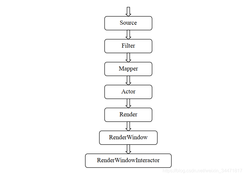
neral framework is shown in the figure. Source is the beginning of the whole pipeline. Source data is first generated by reading files and other means. Filter can have a number of data input, and can produce a number of data output, is a relatively independent calculation module, the function is to make a variety of data transformation. Mapper converts the data processed by the Filter into graph data, and realizes the mapping relationship from data to graph, which is the interface between the visualization pipeline and the graph model. Only mapping relation is obviously not enough. In order to see the real image, Actor is also needed, whose function is to materialize the mapping relation obtained by Mapper, so that people can see the final drawing result. Actor can also control the display properties of the image to make the image appear more realistic by calling the property object (VTKProperty). The next step is for Render and RenderWindow to display the image on the computer window. By calling the graphics engine they provide and the interface between the computer window system, the drawn graphics can be displayed in the window. RenderWindowInterActor is used to realize the interaction between the user and the image, so that the image can be rotated through the mouse operation, and it is convenient to observe the image from all angles.
W.J.S chroeder, K.M.M artin, W.E.L orensen, The Visualization Toolkit – An 0 bject Oriented Approach to 3 d Graphics, Prentice Hall, Upper Richard River, NJ, 1996. ↩ ︎ Shi Yu. Research and implementation of Visualization technology based on VTK [D]. Xian building university of science and technology, 2009.6. ↩ ︎ Schroeder W, Martin K, Lorensen B.T he the Visualization Toolkit an Object – oriented Approach to 3 D Graphics [M]. Prentice Hall: Kitware Inc, 2002. ↩ ︎ qing-gong xu, chang-hua li. VTK Discussion on Frame Structure and Operation Mechanism [J]. Journal of luoyang institute of technology (natural science edition), 2008, 19 (1) : 67-70. ↩ ︎ huang shanshan, wang liang, xiao-ping min. Visualization technology based on VTK studies [J]. Journal of China digital medicine, 2008, 3 (1) : 31-34. ↩ ︎ Wu Songjun, peng demobilization. Of 2 d contour line based on VTK 3 d visualization reconstruction [J]. Computer and modern, 2004, (10) : 111-113. ↩ ︎