Prompt a warning message in the title when the compilation of the ongoing project schematic is complete. After a search on the Internet, I found that someone had summed up the problem.
The principle is that the MODE of all the components in the component library cannot match the introduced MODE in PCB. Then what is MODE?
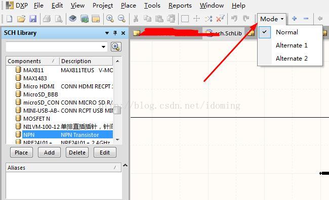
It’s clear when you look at the pictures you bought,

Mode means different view modes.
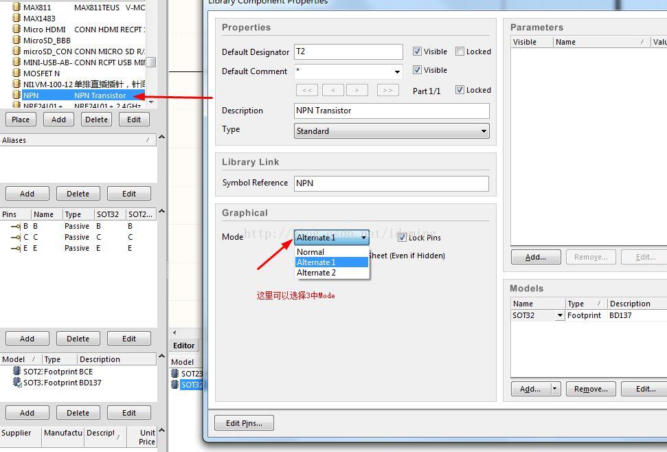
Then quickly open the schematic library in question components. Double-click to open the properties dialog box and you see the following

And then you have here

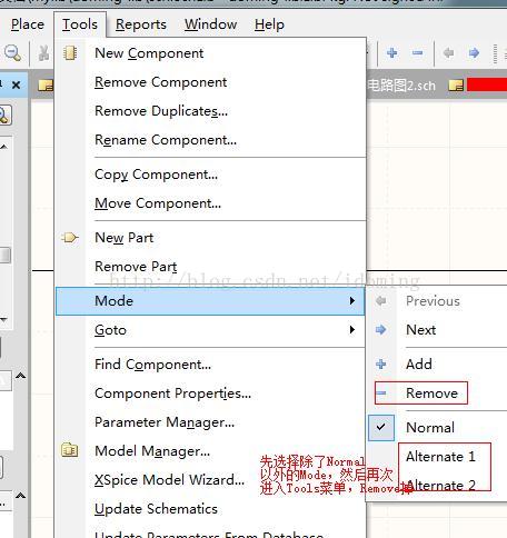
You can also select different views, select different views will find that the number of components pins in the three views is different! The analysis is the problem. The reason for this problem may be that when creating a new component, it is usually copied from other components. Only the component under Normal view is modified, but the component under other MODE is not modified at the same time. Since the device doesn’t need a few views, just delete the other views, leaving only Normal, and you should be OK. (or change the other views to have the same pin as Normal). So how do you delete it?The following figure

After deleting the device according to the above instructions, update the device, compile the schematic project again, and find that the problem is no longer there!